HP 6125XLG R2306-HP 6125XLG Blade Switch Layer 3 - IP Services Command Referen - Page 239
Table 56, Command output, Display detailed information about interface Tunnel 1.
 |
View all HP 6125XLG manuals
Add to My Manuals
Save this manual to your list of manuals |
Page 239 highlights
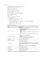
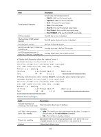
Examples # Display detailed information about interface Tunnel 1. display interface tunnel 1 Tunnel1 current state: UP Line protocol current state: UP Description: Tunnel1 Interface The Maximum Transmit Unit is 1456 Internet Address is 10.1.2.1/24 Primary Tunnel source 2002::1:1, destination 2001::2:1 Tunnel bandwidth 64 (kbps) Tunnel TTL 255 Tunnel protocol/transport GRE/IPv6 GRE key disabled Checksumming of GRE packets disabled Last clearing of counters: Never Last 300 seconds input rate: 0 bytes/sec, 0 bits/sec, 0 packets/sec Last 300 seconds output rate: 0 bytes/sec, 0 bits/sec, 0 packets/sec 0 packets input, 0 bytes, 0 drops 0 packets output, 0 bytes, 0 drops Table 56 Command output Field Tunnel1 current state Line protocol current state Description Maximum Transmit Unit Internet Address Tunnel source destination Tunnel bandwidth Tunnel TTL Description Physical state of the tunnel interface: • Administratively DOWN-The interface has been shut down by the shutdown command. • DOWN-The interface is administratively up but its physical state is down. • UP-Both the administrative and physical states of the interface are up. Link layer state of the tunnel interface: • DOWN-The protocol state of the interface is down. • UP-The protocol state of the interface is up. Description of the tunnel interface. MTU of the tunnel interface. IP address of the tunnel interface. If no IP address is assigned to the interface, this field displays Internet protocol processing : disabled, and the tunnel interface cannot process packets. Primary indicates it is the primary IP address of the interface. Source address of the tunnel. Destination address of the tunnel. Bandwidth of the tunnel interface. TTL of tunneled packets. 231
-
 1
1 -
2
-
3
-
4
-
5
-
6
-
7
-
8
-
9
-
10
-
11
-
12
-
13
-
14
-
15
-
16
-
17
-
18
-
19
-
20
-
21
-
22
-
23
-
24
-
25
-
26
-
27
-
28
-
29
-
30
-
31
-
32
-
33
-
34
-
35
-
36
-
37
-
38
-
39
-
40
-
41
-
42
-
43
-
44
-
45
-
46
-
47
-
48
-
49
-
50
-
51
-
52
-
53
-
54
-
55
-
56
-
57
-
58
-
59
-
60
-
61
-
62
-
63
-
64
-
65
-
66
-
67
-
68
-
69
-
70
-
71
-
72
-
73
-
74
-
75
-
76
-
77
-
78
-
79
-
80
-
81
-
82
-
83
-
84
-
85
-
86
-
87
-
88
-
89
-
90
-
91
-
92
-
93
-
94
-
95
-
96
-
97
-
98
-
99
-
100
-
101
-
102
-
103
-
104
-
105
-
106
-
107
-
108
-
109
-
110
-
111
-
112
-
113
-
114
-
115
-
116
-
117
-
118
-
119
-
120
-
121
-
122
-
123
-
124
-
125
-
126
-
127
-
128
-
129
-
130
-
131
-
132
-
133
-
134
-
135
-
136
-
137
-
138
-
139
-
140
-
141
-
142
-
143
-
144
-
145
-
146
-
147
-
148
-
149
-
150
-
151
-
152
-
153
-
154
-
155
-
156
-
157
-
158
-
159
-
160
-
161
-
162
-
163
-
164
-
165
-
166
-
167
-
168
-
169
-
170
-
171
-
172
-
173
-
174
-
175
-
176
-
177
-
178
-
179
-
180
-
181
-
182
-
183
-
184
-
185
-
186
-
187
-
188
-
189
-
190
-
191
-
192
-
193
-
194
-
195
-
196
-
197
-
198
-
199
-
200
-
201
-
202
-
203
-
204
-
205
-
206
-
207
-
208
-
209
-
210
-
211
-
212
-
213
-
214
-
215
-
216
-
217
-
218
-
219
-
220
-
221
-
222
-
223
-
224
-
225
-
226
-
227
-
228
-
229
-
230
-
231
-
232
-
233
-
 234
234 -
 235
235 -
 236
236 -
 237
237 -
 238
238 -
 239
239 -
 240
240 -
 241
241 -
 242
242 -
 243
243 -
 244
244 -
245
-
246
-
247
-
248
-
249
-
250
-
251
-
252
-
253
-
254
-
255
-
256
-
257
 |
 |