HP C3916A HP LaserJet 5, 5M, and 5N Printer - User's Guide - Page 184
Continued on the next
 |
View all HP C3916A manuals
Add to My Manuals
Save this manual to your list of manuals |
Page 184 highlights
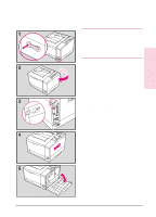
D-8 Printer Memory 6 Loosen the captive screw holding the SIMM door with a Phillips #2 screwdriver. Open the SIMM door. 7 Note the four SIMM slots (a PostScript SIMM will already be installed in a slot in the HP LaserJet 5M). For easiest installation, fill the slots from right to left, starting with slot 1 (see inset). 8 Remove the SIMM board from the antistatic package. Hold the board with your forefingers on the side edges and your thumbs against the back edge. Hold the board so the notch on one end is on the bottom and the metal teeth face toward the SIMM slot. 9 Hold the SIMM board at a 30-degree angle to the slot and push the edge of the board evenly and firmly into the slot (see A). Rotate the SIMM board to the right until the board "clicks" into the metal locking tabs, securing the board in place (see B). Close the SIMM door and tighten the screw (see picture 6). Set the bottom of the right side panel onto the printer. Make sure the three bottom tabs on the panel align with the corresponding slots on the printer. Fold the cover up. The printer is now in the same condition as picture 4. 10 Slide the panel to the left until it becomes firm (1/4 inch gap (7 mm) remaining). Tighten the screw in the upper left corner on the back panel. This will close the remaining gap between the panel and the frame. Continued on the next page EN
-
 1
1 -
2
-
3
-
4
-
5
-
6
-
7
-
8
-
9
-
10
-
11
-
12
-
13
-
14
-
15
-
16
-
17
-
18
-
19
-
20
-
21
-
22
-
23
-
24
-
25
-
26
-
27
-
28
-
29
-
30
-
31
-
32
-
33
-
34
-
35
-
36
-
37
-
38
-
39
-
40
-
41
-
42
-
43
-
44
-
45
-
46
-
47
-
48
-
49
-
50
-
51
-
52
-
53
-
54
-
55
-
56
-
57
-
58
-
59
-
60
-
61
-
62
-
63
-
64
-
65
-
66
-
67
-
68
-
69
-
70
-
71
-
72
-
73
-
74
-
75
-
76
-
77
-
78
-
79
-
80
-
81
-
82
-
83
-
84
-
85
-
86
-
87
-
88
-
89
-
90
-
91
-
92
-
93
-
94
-
95
-
96
-
97
-
98
-
99
-
100
-
101
-
102
-
103
-
104
-
105
-
106
-
107
-
108
-
109
-
110
-
111
-
112
-
113
-
114
-
115
-
116
-
117
-
118
-
119
-
120
-
121
-
122
-
123
-
124
-
125
-
126
-
127
-
128
-
129
-
130
-
131
-
132
-
133
-
134
-
135
-
136
-
137
-
138
-
139
-
140
-
141
-
142
-
143
-
144
-
145
-
146
-
147
-
148
-
149
-
150
-
151
-
152
-
153
-
154
-
155
-
156
-
157
-
158
-
159
-
160
-
161
-
162
-
163
-
164
-
165
-
166
-
167
-
168
-
169
-
170
-
171
-
172
-
173
-
174
-
175
-
176
-
177
-
178
-
 179
179 -
 180
180 -
 181
181 -
 182
182 -
 183
183 -
 184
184 -
 185
185 -
 186
186 -
 187
187 -
 188
188 -
 189
189 -
190
-
191
-
192
-
193
-
194
-
195
-
196
-
197
-
198
-
199
-
200
-
201
-
202
-
203
-
204
-
205
-
206
-
207
-
208
 |
 |
