Yamaha M7CL M7cl V3 Owner's Manual - Page 235
Setting the date and time of the internal clock
 |
View all Yamaha M7CL manuals
Add to My Manuals
Save this manual to your list of manuals |
Page 235 highlights
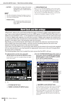
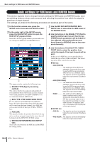
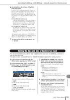
Basic settings for MIX buses and MATRIX buses • Setting the date and time of the internal clock 6 As desired, turn the buttons of the PAN LINK field on/off. In the PAN LINK field, you can specify whether the panning of the signal routed from an input channel to the stereo bus will be linked with operation of the INPUT TO ST PAN knob (if the input channel's SIGNAL TYPE is set to STEREO and BUS TYPE is set to VARI). ● If the PAN LINK button is on If the send-destination bus is stereo, the PAN knob that appears in the location of the SEND LEVEL knob in the input channel's screens will be linked with operation of the INPUT TO ST PAN knob. ● If the PAN LINK button is off The PAN knob that appears in the location of the SEND LEVEL knob in the input channel's screens will be linked with operation of the INPUT TO ST PAN knob. This parameter can be enabled only if the SIGNAL TYPE of the corresponding bus is STEREO (and for a MIX bus, the BUS TYPE must also be VARI). 7 To return to the SETUP screen, press the "×" symbol. Setting the date and time of the internal clock This section explains how to set the date and time of the clock built into the M7CL, and how to view the date and time. The date and time you specify here will affect the time stamp used when saving a scene. 1 In the function access area, press the SETUP button to access the SETUP screen. 2 Press the DATE/TIME button located in the bottom row of the SETUP screen, to open the DATE/TIME popup window. 1 2 3 3 In the DISPLAY FORMAT field, press the MODE button several times to select the desired format for date and time display. You can select from the following display formats. ● Date MM/DD/YYYY(Month/Day/Year) DD/MM/YYYY(Day/Month/Year) YYYY/MM/DD(Year/Month/Day) ● Time 24Hours (hours shown in a range of 0-23) 12Hours (hours shown from AM 0-AM 11 and PM 0-PM 11) 20 Other functions The popup window includes the following items. 1 DATE Specifies the date of the internal clock. B TIME Specifies the time of the internal clock. C DISPLAY FORMAT Specifies the format in which the time of the internal clock is shown. 4 Use multifunction encoders 1-6 on the top panel to specify the current date and time. 5 When you have finished making settings, press the OK button. The date, time, and display format you specified will be finalized, and the popup window will close. If you press the CANCEL button or the "×" symbol instead of the OK button, your changes will be discarded and the popup window will close. M7CL Owner's Manual 235
-
 1
1 -
2
-
3
-
4
-
5
-
6
-
7
-
8
-
9
-
10
-
11
-
12
-
13
-
14
-
15
-
16
-
17
-
18
-
19
-
20
-
21
-
22
-
23
-
24
-
25
-
26
-
27
-
28
-
29
-
30
-
31
-
32
-
33
-
34
-
35
-
36
-
37
-
38
-
39
-
40
-
41
-
42
-
43
-
44
-
45
-
46
-
47
-
48
-
49
-
50
-
51
-
52
-
53
-
54
-
55
-
56
-
57
-
58
-
59
-
60
-
61
-
62
-
63
-
64
-
65
-
66
-
67
-
68
-
69
-
70
-
71
-
72
-
73
-
74
-
75
-
76
-
77
-
78
-
79
-
80
-
81
-
82
-
83
-
84
-
85
-
86
-
87
-
88
-
89
-
90
-
91
-
92
-
93
-
94
-
95
-
96
-
97
-
98
-
99
-
100
-
101
-
102
-
103
-
104
-
105
-
106
-
107
-
108
-
109
-
110
-
111
-
112
-
113
-
114
-
115
-
116
-
117
-
118
-
119
-
120
-
121
-
122
-
123
-
124
-
125
-
126
-
127
-
128
-
129
-
130
-
131
-
132
-
133
-
134
-
135
-
136
-
137
-
138
-
139
-
140
-
141
-
142
-
143
-
144
-
145
-
146
-
147
-
148
-
149
-
150
-
151
-
152
-
153
-
154
-
155
-
156
-
157
-
158
-
159
-
160
-
161
-
162
-
163
-
164
-
165
-
166
-
167
-
168
-
169
-
170
-
171
-
172
-
173
-
174
-
175
-
176
-
177
-
178
-
179
-
180
-
181
-
182
-
183
-
184
-
185
-
186
-
187
-
188
-
189
-
190
-
191
-
192
-
193
-
194
-
195
-
196
-
197
-
198
-
199
-
200
-
201
-
202
-
203
-
204
-
205
-
206
-
207
-
208
-
209
-
210
-
211
-
212
-
213
-
214
-
215
-
216
-
217
-
218
-
219
-
220
-
221
-
222
-
223
-
224
-
225
-
226
-
227
-
228
-
229
-
 230
230 -
 231
231 -
 232
232 -
 233
233 -
 234
234 -
 235
235 -
 236
236 -
 237
237 -
 238
238 -
 239
239 -
 240
240 -
241
-
242
-
243
-
244
-
245
-
246
-
247
-
248
-
249
-
250
-
251
-
252
-
253
-
254
-
255
-
256
-
257
-
258
-
259
-
260
-
261
-
262
-
263
-
264
-
265
-
266
-
267
-
268
-
269
-
270
-
271
-
272
-
273
-
274
-
275
-
276
-
277
-
278
-
279
-
280
-
281
-
282
-
283
-
284
-
285
-
286
-
287
-
288
-
289
-
290
-
291
-
292
-
293
-
294
-
295
-
296
-
297
-
298
-
299
-
300
-
301
-
302
-
303
-
304
-
305
-
306
-
307
-
308
-
309
-
310
-
311
-
312
 |
 |
