Yamaha M7CL M7cl V3 Owner's Manual - Page 294
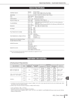
Analog Output Characteristics, Digital Input & Output Characteristics, Control I/O Characteristics
 |
View all Yamaha M7CL manuals
Add to My Manuals
Save this manual to your list of manuals |
Page 294 highlights
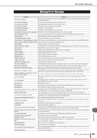
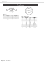
Input/output characteristics ❏ Analog Output Characteristics Output Terminals Actual Source Impedance OMNI OUT 1-16 OMNI OUT 1-8 75 Ω PHONES 15 Ω For Use With Nominal 600 Ω Lines 8 Ω Phones 40 Ω Phones GAIN SW*3 +24 dB (default) +18 dB - Output Level Nominal Max. Before Clip Connector +4 dBu (1.23 V) +24 dBu (12.3 V) XLR-3-32 type -2 dBu (616 mV) +18 dBu (6.16 V) (Balanced)*1 75 mW*4 65 mW*4 150 mW 150 mW Stereo Phone Jack (TRS) (Unbalanced)*2 *1. XLR-3-32 type connectors are balanced. (1=GND, 2=HOT, 3=COLD) *2. PHONES stereo phone jack is unbalanced. (Tip=LEFT, Ring=RIGHT, Sleeve=GND) *3. There are switches inside the body to preset the maximum output level. *4. The position of the level control is 10 dB lowered from Max. * In these specifications, 0 dBu = 0.775 Vrms. * All output DA converters are 24 bit, 128 times oversampling. ❏ Digital Input & Output Characteristics Terminal 2TR OUT DIGITAL*1 AES/EBU EtherSound Format Data Length AES/EBU Professional Use*1 24 bit Ethersound 24 bit Level RS422 100Base-TX Audio Connector - XLR-3-32 type (Balanced)*2 48ch Input/24ch Output @48kHz etherCON *3 *1. The channel status of 2TR OUT DIGITAL is described on page 294. *2. XLR-3-32 type connectors are balanced. (1=GND, 2=HOT, 3=COLD) *3. IN, OUT • Channel Status of 2TR OUT DIGITAL byte 0 bit field name 0 Block Format 1 Mode 2-4 Emphasis 5 Fs Lock 6-7 Sampling Frequency 0-3 Channel Mode 1 4-7 Users Bit Management 0-2 Use of AUX 2 3-7 Source 3 0-7 Multi Channel 0-1 Digital Audio Reference Signal 2 - 4 3-6 Sampling Frequency 7 Sampling Frequency Scan Flag fixed/variable fixed variable fixed fixed fixed fixed variable fixed data 1 0 0x4 0 0x0 0x3 0x2 0x1 0x1 0x0 0x1 0x00 0x00 0x0 0 0x0 0 description professional use audio off lock others 32 kHz 44.1 kHz 48 kHz 2ch mode - 24 bits Audio Data - - - others - ❏ Control I/O Characteristics Terminal NETWORK 3rd Port MIDI IN OUT WORD CLOCK IN OUT REMOTE LAMP 1 (32ch), 2 (48ch) USB HOST Format IEEE802.3 MIDI - - - USB 1.1 *1. 4pin=HOT, 3pin=COLD, Lamp rating 5 W, Voltage control by software Level - TTL/75Ω TTL/75Ω RS422 0 V - 12 V - RJ-45 Connector DIN Connector 5P BNC Connector D-Sub Connector 9P (Male) XLR-4-31 type*1 A type USB Connector 294 M7CL Owner's Manual
-
 1
1 -
2
-
3
-
4
-
5
-
6
-
7
-
8
-
9
-
10
-
11
-
12
-
13
-
14
-
15
-
16
-
17
-
18
-
19
-
20
-
21
-
22
-
23
-
24
-
25
-
26
-
27
-
28
-
29
-
30
-
31
-
32
-
33
-
34
-
35
-
36
-
37
-
38
-
39
-
40
-
41
-
42
-
43
-
44
-
45
-
46
-
47
-
48
-
49
-
50
-
51
-
52
-
53
-
54
-
55
-
56
-
57
-
58
-
59
-
60
-
61
-
62
-
63
-
64
-
65
-
66
-
67
-
68
-
69
-
70
-
71
-
72
-
73
-
74
-
75
-
76
-
77
-
78
-
79
-
80
-
81
-
82
-
83
-
84
-
85
-
86
-
87
-
88
-
89
-
90
-
91
-
92
-
93
-
94
-
95
-
96
-
97
-
98
-
99
-
100
-
101
-
102
-
103
-
104
-
105
-
106
-
107
-
108
-
109
-
110
-
111
-
112
-
113
-
114
-
115
-
116
-
117
-
118
-
119
-
120
-
121
-
122
-
123
-
124
-
125
-
126
-
127
-
128
-
129
-
130
-
131
-
132
-
133
-
134
-
135
-
136
-
137
-
138
-
139
-
140
-
141
-
142
-
143
-
144
-
145
-
146
-
147
-
148
-
149
-
150
-
151
-
152
-
153
-
154
-
155
-
156
-
157
-
158
-
159
-
160
-
161
-
162
-
163
-
164
-
165
-
166
-
167
-
168
-
169
-
170
-
171
-
172
-
173
-
174
-
175
-
176
-
177
-
178
-
179
-
180
-
181
-
182
-
183
-
184
-
185
-
186
-
187
-
188
-
189
-
190
-
191
-
192
-
193
-
194
-
195
-
196
-
197
-
198
-
199
-
200
-
201
-
202
-
203
-
204
-
205
-
206
-
207
-
208
-
209
-
210
-
211
-
212
-
213
-
214
-
215
-
216
-
217
-
218
-
219
-
220
-
221
-
222
-
223
-
224
-
225
-
226
-
227
-
228
-
229
-
230
-
231
-
232
-
233
-
234
-
235
-
236
-
237
-
238
-
239
-
240
-
241
-
242
-
243
-
244
-
245
-
246
-
247
-
248
-
249
-
250
-
251
-
252
-
253
-
254
-
255
-
256
-
257
-
258
-
259
-
260
-
261
-
262
-
263
-
264
-
265
-
266
-
267
-
268
-
269
-
270
-
271
-
272
-
273
-
274
-
275
-
276
-
277
-
278
-
279
-
280
-
281
-
282
-
283
-
284
-
285
-
286
-
287
-
288
-
 289
289 -
 290
290 -
 291
291 -
 292
292 -
 293
293 -
 294
294 -
 295
295 -
 296
296 -
 297
297 -
 298
298 -
 299
299 -
300
-
301
-
302
-
303
-
304
-
305
-
306
-
307
-
308
-
309
-
310
-
311
-
312
 |
 |
