Brother International LT2-B845 MKII Instruction Manual - Multi - Page 87
verschieben
 |
View all Brother International LT2-B845 MKII manuals
Add to My Manuals
Save this manual to your list of manuals |
Page 87 highlights
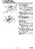
0.2 mm C C C 13. INSTALLING OPTIONAL PARTS 13. ANBRINGEN VON ZUBEHORTEILEN 13. INSTALLATION DES PIECES EN OPTION 13. INSTALACION DE PIEZAS OPCIONALES 0.6-0.9 mm 4. Return the machine head to its original position. 5. Install the opener 0. 6. Install the feed dog 0. 7. Install the needle plate 0. 0 8. Install the presser foot 0. 9. Loosen the set screws 0 and move the rotary hook up and down to adjust so that the clearance between the rotary hook 0 and the needle plate 0 is 0.6-0.9 mm. NOTE: Do not turn the rotary hook while the set screws 0 are loosened, otherwise it will change the timing between the needle and the rotary hook. 0 10. Tighten the set screws 0. 11. Loosen the set screws and move the opener 0 to the left or right to adjust so that the clearance between 0 the rotary hook and the opener 0 is 0.2 mm when the opener 0 is pulled as far as it will go in the direction of the arrow. 12. Tighten the set screws 0. 13. Install the slide plates 0. 14. Add 1-2 drops of oil to the left and right rotary hook races 0. 15. Adjust the rotary hook lubrication amount while refer- ring to page 61. 4. Klappen Sie das Maschienenoberteil wieder zuruck. 4iP 5. Montieren Sie den Fadenspreizer 0. 6. Montieren Sie den Transporteur 0. 7. Bringen Sie die Stichplatte 0 an. 8. Bringen Sie den Stoffdriickerfull 0 an. 9. Losen Sie die Schrauben p und stellen Sie den Greifer 0 so ein, dal der Abstand zwischen dem Greifer m und der Stichplatte 0 0,6-0,9 mm betragt. HINWEIS: Wenn die Schrauben 0 gelost sind, dart der Greifer nicht gedreht werden, well dadurch die Synchronisation zwischen der Nadel und dem Greifer verstellt wird. 10. Ziehen Sie die Schrauben 0 wieder fest. 11. L6sen Sie die Schrauben und verschieben Sie den Fadenspreizer 0 seitlich, so dal3 der Abstand zwischen • dem Greifer und dem Fadenspreizer 0 0,2 mm betragt, wenn der Fadenspreizer 0 ganz in Pfeilrichtung gezogen wird. 12. Ziehen Sie die Schrauben (D fest. 13. Bringen Sie die Schiebeplatten 0 an. 14. Tragen Sie 1-2 Tropfen O1 auf den linken und rechten Greiferlaufring 0 auf. 15. Stellen Sie die Greiferschmierung wie auf Seite 61 beschrieben ein. - 72 - Model No. LT2-5840 Mark II LT2-9870 Mark II
-
 1
1 -
2
-
3
-
4
-
5
-
6
-
7
-
8
-
9
-
10
-
11
-
12
-
13
-
14
-
15
-
16
-
17
-
18
-
19
-
20
-
21
-
22
-
23
-
24
-
25
-
26
-
27
-
28
-
29
-
30
-
31
-
32
-
33
-
34
-
35
-
36
-
37
-
38
-
39
-
40
-
41
-
42
-
43
-
44
-
45
-
46
-
47
-
48
-
49
-
50
-
51
-
52
-
53
-
54
-
55
-
56
-
57
-
58
-
59
-
60
-
61
-
62
-
63
-
64
-
65
-
66
-
67
-
68
-
69
-
70
-
71
-
72
-
73
-
74
-
75
-
76
-
77
-
78
-
79
-
80
-
81
-
 82
82 -
 83
83 -
 84
84 -
 85
85 -
 86
86 -
 87
87 -
 88
88 -
 89
89 -
 90
90 -
 91
91 -
 92
92 -
93
-
94
-
95
-
96
-
97
-
98
 |
 |
