D-Link DWS-3160-24TC DWS-3160 Series Web UI Reference Guide - Page 430
L3 Tunnel Status, Redirect URL
 |
View all D-Link DWS-3160-24TC manuals
Add to My Manuals
Save this manual to your list of manuals |
Page 430 highlights
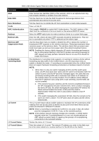
DWS-3160 Series Gigabit Ethernet Unified Switch Web UI Reference Guide Parameter SSID Hide SSID Deny Broadcast VLAN MAC Authentication Redirect Redirect URL Wireless ARP Suppression Mode L2 Distributed Tunneling Mode L3 Tunnel L3 Tunnel Status L3 Tunnel Subnet Description Enter Service Set Identifier (SSID) of the network, which is an alphanumeric key that uniquely identifies a wireless local area network. Tick the check box to hide the SSID broadcast to discourage stations from automatically discovering the access point. Tick the check box to prohibit the AP from responding to client probe requests Enter a VLAN ID. Click Local or RADIUS to enable MAC Authentication. The MAC address of the client must be configured at the local switch or the external RADIUS server. Select the HTTP radio button to redirect wireless clients to a custom Web page. Enter the URL where all initial HTTP accesses should be redirected to. This text box is accessible only when HTTP is selected as the redirect type. Use the drop-down menu to enable or disable the APs to reduce the number of broadcasted ARP requests on the wireless interfaces. Reducing broadcasts helps conserve power on the wireless clients. The wireless clients that use power-save mode must wake up and use more power when they detect broadcast frames. NOTE: Enabling this feature slightly degrades AP packet forwarding performance due to extra packet filtering to find DHCP packets and extra processing for ARP request and reply packets. Networks that do not use IPv4 should not enable this feature. The distributed L2 tunneling mode supports L3 roaming for wireless clients without forwarding any data traffic to the Unified Switch. Use the drop-down menu to enable or disable the mode. L2 tunneling is recommended when the Unified Switch does not support hardware forwarding acceleration or hardware-based L2 tunnels. NOTE: 1. When there is only one switch managing all APs and that switch goes down, all APs shut down their radios and the tunnel is terminated. After the switch recovers and the AP becomes managed again, the client that was previously tunneling traffic will re-associate and obtain an IP address on the network where its currently located. This IP address will be different from the IP address it was using when it was tunneling, and the traffic will not be tunneled. 2. If the network has peer switches and the tunnel is established between the APs managed by the peer switches then, when a switch managing the home AP fails, the switch managing the association AP detects the failure and terminates the tunnel. At this point the client is disassociated. When the client re-associates it obtains a new IP address. 3. If the switch managing the association AP fails, then the scenario is the same as in item 1 above. The AP takes down all radios and the clients disassociate. The L3 Tunnel feature allows mobile stations to maintain their IP connections while roaming from one access point to another access point even when these access points are attached to different IP subnets. NOTE: When L3 tunneling is enabled the VLAN ID is not used. In fact, the switch puts the management VLAN ID, if any, on the tunneled packets. NOTE: If the wireless network topology changes (for example, a Unified Switch reboots) while the L3 tunneling feature is in use, you should perform an ARP refresh on wired clients to speed up the process of re-establishing connectivity to the tunneled network. Display the status of L3 tunnel. Enter the subnet of L3 tunnel. The network IP address you enter in this field must be in the same subnet as a routing interface for the WLAN on the Switch. 425
-
 1
1 -
2
-
3
-
4
-
5
-
6
-
7
-
8
-
9
-
10
-
11
-
12
-
13
-
14
-
15
-
16
-
17
-
18
-
19
-
20
-
21
-
22
-
23
-
24
-
25
-
26
-
27
-
28
-
29
-
30
-
31
-
32
-
33
-
34
-
35
-
36
-
37
-
38
-
39
-
40
-
41
-
42
-
43
-
44
-
45
-
46
-
47
-
48
-
49
-
50
-
51
-
52
-
53
-
54
-
55
-
56
-
57
-
58
-
59
-
60
-
61
-
62
-
63
-
64
-
65
-
66
-
67
-
68
-
69
-
70
-
71
-
72
-
73
-
74
-
75
-
76
-
77
-
78
-
79
-
80
-
81
-
82
-
83
-
84
-
85
-
86
-
87
-
88
-
89
-
90
-
91
-
92
-
93
-
94
-
95
-
96
-
97
-
98
-
99
-
100
-
101
-
102
-
103
-
104
-
105
-
106
-
107
-
108
-
109
-
110
-
111
-
112
-
113
-
114
-
115
-
116
-
117
-
118
-
119
-
120
-
121
-
122
-
123
-
124
-
125
-
126
-
127
-
128
-
129
-
130
-
131
-
132
-
133
-
134
-
135
-
136
-
137
-
138
-
139
-
140
-
141
-
142
-
143
-
144
-
145
-
146
-
147
-
148
-
149
-
150
-
151
-
152
-
153
-
154
-
155
-
156
-
157
-
158
-
159
-
160
-
161
-
162
-
163
-
164
-
165
-
166
-
167
-
168
-
169
-
170
-
171
-
172
-
173
-
174
-
175
-
176
-
177
-
178
-
179
-
180
-
181
-
182
-
183
-
184
-
185
-
186
-
187
-
188
-
189
-
190
-
191
-
192
-
193
-
194
-
195
-
196
-
197
-
198
-
199
-
200
-
201
-
202
-
203
-
204
-
205
-
206
-
207
-
208
-
209
-
210
-
211
-
212
-
213
-
214
-
215
-
216
-
217
-
218
-
219
-
220
-
221
-
222
-
223
-
224
-
225
-
226
-
227
-
228
-
229
-
230
-
231
-
232
-
233
-
234
-
235
-
236
-
237
-
238
-
239
-
240
-
241
-
242
-
243
-
244
-
245
-
246
-
247
-
248
-
249
-
250
-
251
-
252
-
253
-
254
-
255
-
256
-
257
-
258
-
259
-
260
-
261
-
262
-
263
-
264
-
265
-
266
-
267
-
268
-
269
-
270
-
271
-
272
-
273
-
274
-
275
-
276
-
277
-
278
-
279
-
280
-
281
-
282
-
283
-
284
-
285
-
286
-
287
-
288
-
289
-
290
-
291
-
292
-
293
-
294
-
295
-
296
-
297
-
298
-
299
-
300
-
301
-
302
-
303
-
304
-
305
-
306
-
307
-
308
-
309
-
310
-
311
-
312
-
313
-
314
-
315
-
316
-
317
-
318
-
319
-
320
-
321
-
322
-
323
-
324
-
325
-
326
-
327
-
328
-
329
-
330
-
331
-
332
-
333
-
334
-
335
-
336
-
337
-
338
-
339
-
340
-
341
-
342
-
343
-
344
-
345
-
346
-
347
-
348
-
349
-
350
-
351
-
352
-
353
-
354
-
355
-
356
-
357
-
358
-
359
-
360
-
361
-
362
-
363
-
364
-
365
-
366
-
367
-
368
-
369
-
370
-
371
-
372
-
373
-
374
-
375
-
376
-
377
-
378
-
379
-
380
-
381
-
382
-
383
-
384
-
385
-
386
-
387
-
388
-
389
-
390
-
391
-
392
-
393
-
394
-
395
-
396
-
397
-
398
-
399
-
400
-
401
-
402
-
403
-
404
-
405
-
406
-
407
-
408
-
409
-
410
-
411
-
412
-
413
-
414
-
415
-
416
-
417
-
418
-
419
-
420
-
421
-
422
-
423
-
424
-
 425
425 -
 426
426 -
 427
427 -
 428
428 -
 429
429 -
 430
430 -
 431
431 -
 432
432 -
 433
433 -
 434
434 -
 435
435 -
436
-
437
-
438
-
439
-
440
-
441
-
442
-
443
-
444
-
445
-
446
-
447
-
448
-
449
-
450
-
451
-
452
-
453
-
454
-
455
-
456
-
457
-
458
-
459
-
460
-
461
-
462
-
463
-
464
-
465
-
466
-
467
-
468
-
469
-
470
-
471
-
472
-
473
-
474
-
475
-
476
-
477
-
478
-
479
-
480
-
481
-
482
-
483
-
484
-
485
-
486
-
487
-
488
-
489
-
490
-
491
-
492
-
493
-
494
-
495
-
496
-
497
-
498
-
499
-
500
-
501
-
502
-
503
-
504
-
505
 |
 |