Canon EOS C70 Instruction Manual - Page 11
Names of Parts, Camera
 |
View all Canon EOS C70 manuals
Add to My Manuals
Save this manual to your list of manuals |
Page 11 highlights
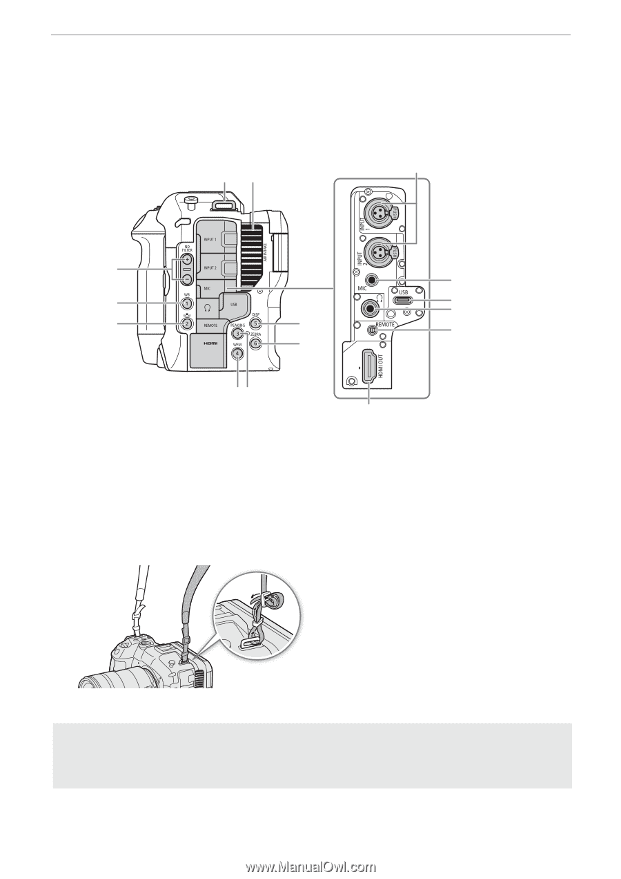
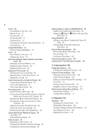
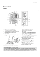
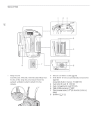
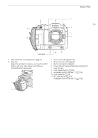
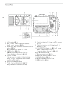
Names of Parts Camera 45 Names of Parts 6 11 1 7 2 8 9 3 11 10 12 13 14 15 1 ND FILTER +/- buttons (A 61) 2 WB (white balance) button (A 66)/ Assignable button Camera 1 (A 105) 3 Å (white balance adjustment) button (A 66)/ Assignable button Camera 2 (A 105) 4 Strap mounts Pass one end of the SS-1200 Shoulder Strap through the strap mount and adjust the length of the strap. * Can be assigned exclusively as a REC button (A 105) 5 Air intake vent (A 39) 6 INPUT 1/INPUT 2 terminals (A 88) 7 MIC (microphone) terminal (A 88) 8 USB terminal For connecting a commercially available Wi-Fi/ Ethernet adapter or the GP-E2 GPS Receiver. 9 × (headphone) terminal (A 93) 10 REMOTE terminal (A 104) For connecting the RC-V100 Remote Controller or commercially available remote controllers. 11 DISP (display) button (A 43)/ Assignable button Camera 5 (A 105) 12 ZEBRA button (A 82)/ Assignable button Camera 6 (A 105) 13 WFM (video scope) button (A 95)/ Assignable button Camera 4* (A 105) 14 PEAKING button (A 71)/ Assignable button Camera 3 (A 105) 15 HDMI OUT terminal (A 128) Removing and attaching the terminal covers You can remove the covers of the camera's terminals to access them more easily. To remove a terminal's cover, open the cover and gently pull it straight out. To attach back the terminal cover, insert the connecting strip into the opening. If the connecting strip is difficult to grasp, use a pair of tweezers or similar tool.
-
 1
1 -
2
-
3
-
4
-
5
-
 6
6 -
 7
7 -
 8
8 -
 9
9 -
 10
10 -
 11
11 -
 12
12 -
 13
13 -
 14
14 -
 15
15 -
 16
16 -
17
-
18
-
19
-
20
-
21
-
22
-
23
-
24
-
25
-
26
-
27
-
28
-
29
-
30
-
31
-
32
-
33
-
34
-
35
-
36
-
37
-
38
-
39
-
40
-
41
-
42
-
43
-
44
-
45
-
46
-
47
-
48
-
49
-
50
-
51
-
52
-
53
-
54
-
55
-
56
-
57
-
58
-
59
-
60
-
61
-
62
-
63
-
64
-
65
-
66
-
67
-
68
-
69
-
70
-
71
-
72
-
73
-
74
-
75
-
76
-
77
-
78
-
79
-
80
-
81
-
82
-
83
-
84
-
85
-
86
-
87
-
88
-
89
-
90
-
91
-
92
-
93
-
94
-
95
-
96
-
97
-
98
-
99
-
100
-
101
-
102
-
103
-
104
-
105
-
106
-
107
-
108
-
109
-
110
-
111
-
112
-
113
-
114
-
115
-
116
-
117
-
118
-
119
-
120
-
121
-
122
-
123
-
124
-
125
-
126
-
127
-
128
-
129
-
130
-
131
-
132
-
133
-
134
-
135
-
136
-
137
-
138
-
139
-
140
-
141
-
142
-
143
-
144
-
145
-
146
-
147
-
148
-
149
-
150
-
151
-
152
-
153
-
154
-
155
-
156
-
157
-
158
-
159
-
160
-
161
-
162
-
163
-
164
-
165
-
166
-
167
-
168
-
169
-
170
-
171
-
172
-
173
-
174
-
175
-
176
-
177
-
178
-
179
-
180
-
181
-
182
-
183
-
184
-
185
-
186
-
187
-
188
-
189
-
190
-
191
-
192
-
193
-
194
-
195
-
196
-
197
-
198
-
199
-
200
-
201
-
202
-
203
-
204
-
205
-
206
-
207
-
208
-
209
-
210
-
211
-
212
-
213
-
214
-
215
 |
 |