Canon EOS C70 Instruction Manual - Page 128
Connecting to an External Monitor or Recorder, Using the HDMI OUT Terminal, etup] > [HDMI Max Re
 |
View all Canon EOS C70 manuals
Add to My Manuals
Save this manual to your list of manuals |
Page 128 highlights
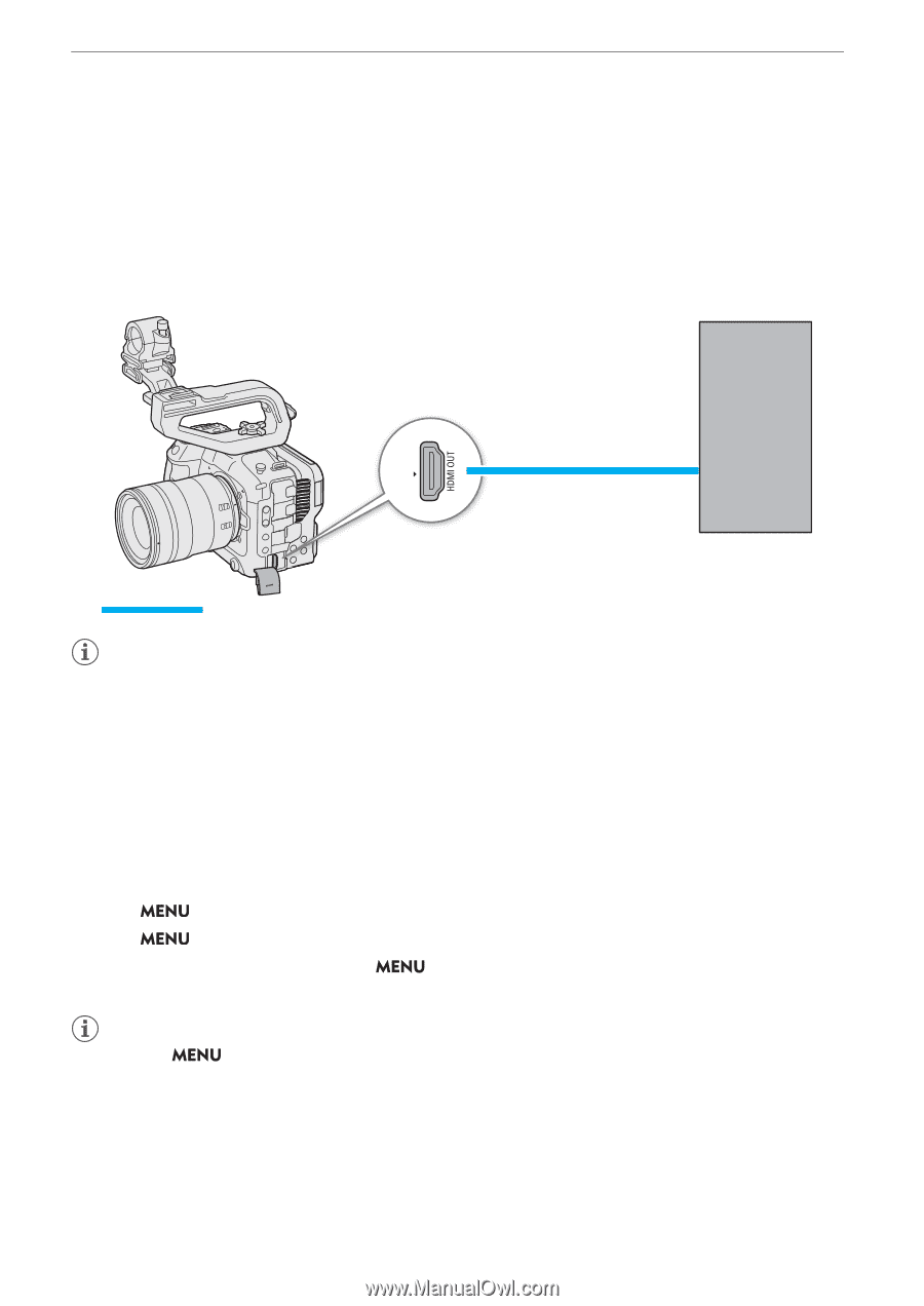
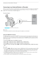
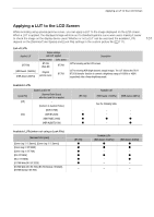
Connecting to an External Monitor or Recorder Connecting to an External Monitor or Recorder When you connect the camera to an external device, be it a monitor (to monitor the recording or for playback) or an external video recorder (for recording), adjust the required settings in the menu. For details about output 128 signals, refer to Video Output Configuration (A 127). Connection diagram External monitor/ digital video recorder HDMI OUT terminal HDMI inputs HDMI cable (commercially available) NOTES • Powering the camera from a power outlet using an AC adapter is recommended. Using the HDMI OUT Terminal The digital signal that is output from the HDMITM OUT terminal includes the video signal and audio signal. You can output also the time code signal, recording command and various assistance displays (onscreen displays, markers, etc.) in order to check them also on an external monitor. In CAMERA mode, the camera's time code can be output as well. 1 Connect the HDMI cable to the HDMI OUT terminal. 2 Select > [B System Setup] > [HDMI Max Res.] > Desired option. 3 Select > [B System Setup] > [HDMI Scan Mode] > Desired option. 4 To output the time code signal, select [On]. > [Æ Recording/Media Setup] > [HDMI Time Code] > NOTES • You can set > [B System Setup] > [Linked to HDMI Monitor] to [On] to automatically change the HDMI OUT terminal's output resolution according to the capabilities of the connected monitor. When this setting is set to [Off], the output resolution is set according to the menu settings and if the connected monitor is not compatible with the signal output from the camera, HDMI output will stop. • The HDMI OUT terminal is for output only. Do not connect the camera to another device's output terminal using the HDMI OUT terminal as this will cause a malfunction. • Correct operation cannot be guaranteed when connecting the camera to DVI monitors.
-
 1
1 -
2
-
3
-
4
-
5
-
6
-
7
-
8
-
9
-
10
-
11
-
12
-
13
-
14
-
15
-
16
-
17
-
18
-
19
-
20
-
21
-
22
-
23
-
24
-
25
-
26
-
27
-
28
-
29
-
30
-
31
-
32
-
33
-
34
-
35
-
36
-
37
-
38
-
39
-
40
-
41
-
42
-
43
-
44
-
45
-
46
-
47
-
48
-
49
-
50
-
51
-
52
-
53
-
54
-
55
-
56
-
57
-
58
-
59
-
60
-
61
-
62
-
63
-
64
-
65
-
66
-
67
-
68
-
69
-
70
-
71
-
72
-
73
-
74
-
75
-
76
-
77
-
78
-
79
-
80
-
81
-
82
-
83
-
84
-
85
-
86
-
87
-
88
-
89
-
90
-
91
-
92
-
93
-
94
-
95
-
96
-
97
-
98
-
99
-
100
-
101
-
102
-
103
-
104
-
105
-
106
-
107
-
108
-
109
-
110
-
111
-
112
-
113
-
114
-
115
-
116
-
117
-
118
-
119
-
120
-
121
-
122
-
 123
123 -
 124
124 -
 125
125 -
 126
126 -
 127
127 -
 128
128 -
 129
129 -
 130
130 -
 131
131 -
 132
132 -
 133
133 -
134
-
135
-
136
-
137
-
138
-
139
-
140
-
141
-
142
-
143
-
144
-
145
-
146
-
147
-
148
-
149
-
150
-
151
-
152
-
153
-
154
-
155
-
156
-
157
-
158
-
159
-
160
-
161
-
162
-
163
-
164
-
165
-
166
-
167
-
168
-
169
-
170
-
171
-
172
-
173
-
174
-
175
-
176
-
177
-
178
-
179
-
180
-
181
-
182
-
183
-
184
-
185
-
186
-
187
-
188
-
189
-
190
-
191
-
192
-
193
-
194
-
195
-
196
-
197
-
198
-
199
-
200
-
201
-
202
-
203
-
204
-
205
-
206
-
207
-
208
-
209
-
210
-
211
-
212
-
213
-
214
-
215
 |
 |