Canon EOS C70 Instruction Manual - Page 95
Video Scopes, Displaying a Video Scope, Changing the Waveform Monitor Settings
 |
View all Canon EOS C70 manuals
Add to My Manuals
Save this manual to your list of manuals |
Page 95 highlights
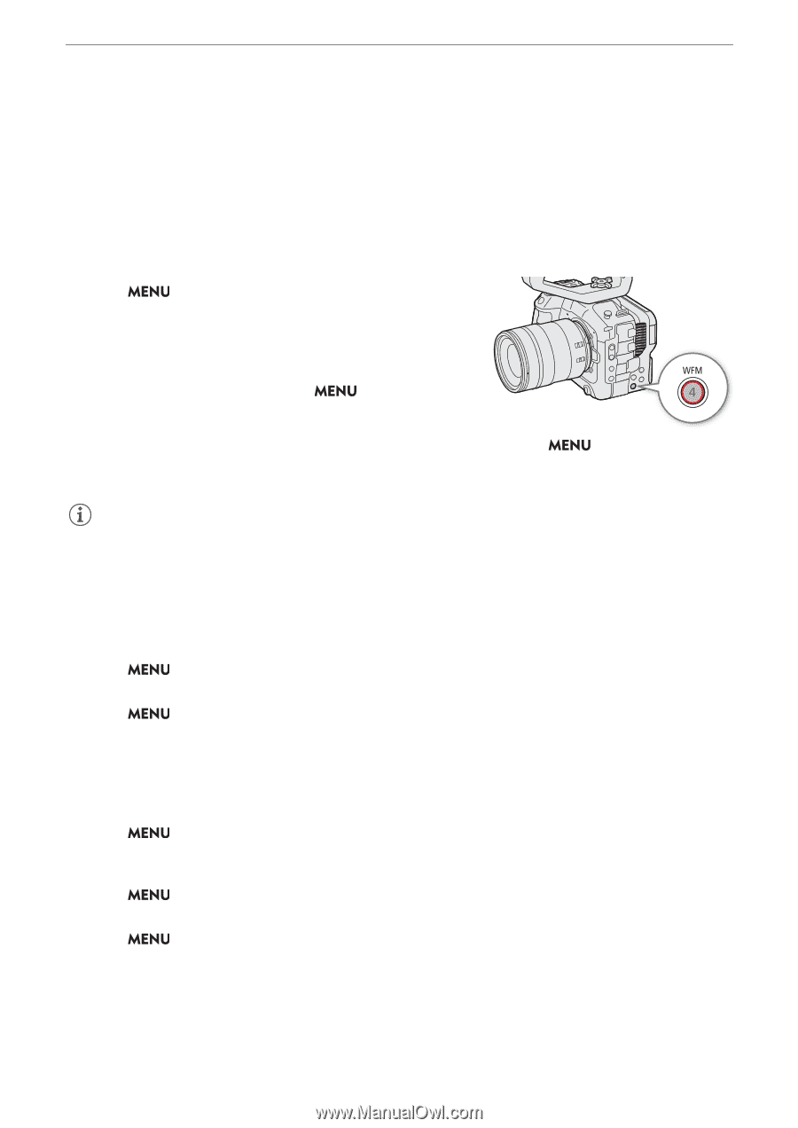
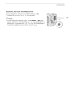
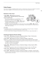
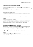
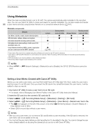
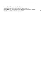
Video Scopes Video Scopes The camera can display a simplified waveform monitor or a vectorscope to check your recordings. The selected video scope is displayed on the screen and can be output to other monitoring devices as well. 95 Displaying a Video Scope 1 Select > [A Assistance Functions] > [WFM Function] > [Waveform Monitor] or [Vectorscope]. 2 Press the WFM button. • You can also use direct touch control (A 49) to turn the [Waveform Monitor]/[Vectorscope] setting on/off. • Alternatively, you can use one of the > [A Assistance Functions] > [WFM:] settings to turn the video scope on/off separately on the desired video output. • By default, the video scope will appear on the right of the screen. Using the > [A Assistance Functions] > [Waveform Settings] or [Vectorscope Settings] > [Position] settings, you can select where to display it (left or right side). NOTES • The waveform monitor will not be affected even if a LUT is applied to the image, the range is changed or anamorphic desqueeze is used on the selected video output or screen. • The video scopes will also be displayed while adjusting a custom picture file's image settings (A 110). Changing the Waveform Monitor Settings 1 Select > [A Assistance Functions] > [Waveform Settings] > [Type] > Desired option. • If you selected an option other than [Select Line], skip to step 4. 2 Select > [A Assistance Functions] > [Waveform Settings] > [Select Line]. 3 Enter the Y coordinate of the red horizontal line to display using the data entry screen (A 25). • The available range of lines that can be selected depends on the vertical component of the resolution used. For 2160: 0 to 2158 (in 2-line increments) For 1080: 0 to 1079 (in 1-line increments) For 720: 0 to 719 (in 1-line increments) 4 Select > [A Assistance Functions] > [Waveform Settings] > [Vertical Scale for HDR] > Desired option. • Select the Y axis (luminance) scale used when displaying the waveform monitor of an HDR image. 5 Select > [A Assistance Functions] > [Waveform Settings] > [Gain] > [1x] or [2x]. • If you selected [1x], the rest of the procedure is not necessary. 6 Select > [A Assistance Functions] > [Waveform Settings] > [Y Position] > Desired option. • The display range of the waveform monitor's Y axis will be reduced by half. Select the minimum luminance value (in %) shown on the Y axis.
-
 1
1 -
2
-
3
-
4
-
5
-
6
-
7
-
8
-
9
-
10
-
11
-
12
-
13
-
14
-
15
-
16
-
17
-
18
-
19
-
20
-
21
-
22
-
23
-
24
-
25
-
26
-
27
-
28
-
29
-
30
-
31
-
32
-
33
-
34
-
35
-
36
-
37
-
38
-
39
-
40
-
41
-
42
-
43
-
44
-
45
-
46
-
47
-
48
-
49
-
50
-
51
-
52
-
53
-
54
-
55
-
56
-
57
-
58
-
59
-
60
-
61
-
62
-
63
-
64
-
65
-
66
-
67
-
68
-
69
-
70
-
71
-
72
-
73
-
74
-
75
-
76
-
77
-
78
-
79
-
80
-
81
-
82
-
83
-
84
-
85
-
86
-
87
-
88
-
89
-
 90
90 -
 91
91 -
 92
92 -
 93
93 -
 94
94 -
 95
95 -
 96
96 -
 97
97 -
 98
98 -
 99
99 -
 100
100 -
101
-
102
-
103
-
104
-
105
-
106
-
107
-
108
-
109
-
110
-
111
-
112
-
113
-
114
-
115
-
116
-
117
-
118
-
119
-
120
-
121
-
122
-
123
-
124
-
125
-
126
-
127
-
128
-
129
-
130
-
131
-
132
-
133
-
134
-
135
-
136
-
137
-
138
-
139
-
140
-
141
-
142
-
143
-
144
-
145
-
146
-
147
-
148
-
149
-
150
-
151
-
152
-
153
-
154
-
155
-
156
-
157
-
158
-
159
-
160
-
161
-
162
-
163
-
164
-
165
-
166
-
167
-
168
-
169
-
170
-
171
-
172
-
173
-
174
-
175
-
176
-
177
-
178
-
179
-
180
-
181
-
182
-
183
-
184
-
185
-
186
-
187
-
188
-
189
-
190
-
191
-
192
-
193
-
194
-
195
-
196
-
197
-
198
-
199
-
200
-
201
-
202
-
203
-
204
-
205
-
206
-
207
-
208
-
209
-
210
-
211
-
212
-
213
-
214
-
215
 |
 |