IBM 4846-545 Service Guide
IBM 4846-545 - SurePOS 500 - 512 MB RAM Manual
 |
View all IBM 4846-545 manuals
Add to My Manuals
Save this manual to your list of manuals |
IBM 4846-545 manual content summary:
- IBM 4846-545 | Service Guide - Page 1
SurePOS 500 Series Hardware Service Guide for Models 545 and 565 SY27-0423-00 - IBM 4846-545 | Service Guide - Page 2
- IBM 4846-545 | Service Guide - Page 3
SurePOS 500 Series Hardware Service Guide for Models 545 and 565 SY27-0423-00 - IBM 4846-545 | Service Guide - Page 4
information and the product it supports, be sure to read "Safety and environmental notices" on page xi and the general information in Appendix D, "Notices," on page 125. First Edition (October 2006) This edition applies to the IBM® SurePOS Machine Type 4846, Models 545 and 565 and to all subsequent - IBM 4846-545 | Service Guide - Page 5
the flash BIOS 18 Diagnosing problems and troubleshooting 19 Researching the Knowledgebase 19 Preliminary checklist 19 Troubleshooting symptoms and actions 20 CMOS recovery 23 Chapter 3. Removing and replacing FRUs for the SurePOS 500 Models 545 and 565 25 © Copyright IBM Corp. 2006 iii - IBM 4846-545 | Service Guide - Page 6
catalog 95 Assembly 1: Models 545 and 565 96 Assembly 2: Countertop and cash drawer keyboard integration tray and filler panels 98 Assembly 3: Optional peripherals 100 Assembly 4: Countertop non-keyboard integration tray and filler panels. . . . 102 iv Models 545 and 565 Hardware Service Guide - IBM 4846-545 | Service Guide - Page 7
Assembly 5: Cash drawer non-keyboard integration tray and filler panels 104 Appendix B. Power cords 107 Appendix C. System specifications and planning 150 Safety Information-German 152 Safety Information-Traditional Chinese 154 Index 157 Glossary 161 Part number index 169 Contents v - IBM 4846-545 | Service Guide - Page 8
vi Models 545 and 565 Hardware Service Guide - IBM 4846-545 | Service Guide - Page 9
from the system board 35 15. Disconnecting the touch cable and removing the front bezel 36 16. View the integration tray 72 47. Overview of integration tray, SurePOS 500, printer, and filler panels 73 48. Connecting keyboard-integration tray on a countertop 80 © Copyright IBM Corp. 2006 vii - IBM 4846-545 | Service Guide - Page 10
display onto the keyboard integration tray SurePOS Models 545 and 565 with counter top tray 111 70. SurePOS Models 545 and 565 with cash drawer tray 112 71. Dimensions of unit with 12-inch display 113 72. Dimensions of unit with 15-inch display 114 viii Models 545 and 565 Hardware Service Guide - IBM 4846-545 | Service Guide - Page 11
supported devices 9 10. SurePOS 500 task information 19 11. Symptoms and actions 20 12. Pictorial overview of common removal tasks 26 13. Service keyboard-integration tray legend 85 19. Power cord lengths and part numbers by country 107 20. Height, weight and depth of the SurePOS 500 Models 545 - IBM 4846-545 | Service Guide - Page 12
x Models 545 and 565 Hardware Service Guide - IBM 4846-545 | Service Guide - Page 13
note provides important tips, guidance, or advice. Safety Information Danger: Before you begin to install this product, read the safety information in IBM Safety Information - Read This First, GA27-4004. This booklet describes safe procedures for cabling and plugging in electrical equipment. Gevaar - IBM 4846-545 | Service Guide - Page 14
dit produkt, dient u eerst de veiligheidsrichtlijnen te lezen die zijn vermeld in de publikatie IBM Safety Information - Read This First, GA27-4004. In dit boekje vindt u veilige procedures blage et brancher les équipements électriques en toute sécurité. xii Models 545 and 565 Hardware Service Guide - IBM 4846-545 | Service Guide - Page 15
wird, die Sicherheitshinweise in Sicherheitsinformationen-Bitte zuerst lesen, IBM Form GA27-4004. Diese Veröffentlichung beschreibt die te. Vigyázat Mielôtt megkezdi a berendezés üzembe helyezését, olvassa el a IBM Safety Information - Read This First, GA27-4004 könyvecskében leírt biztonsági - IBM 4846-545 | Service Guide - Page 16
börjar installera den här produkten bör du läsa säkerhetsinformationen i dikumentet Säkerhetsföreskrifter-Läs detta först, GA27-4004. Där beskrivs hur du på ett säkert sätt ansluter elektrisk utrustning. xiv Models 545 and 565 Hardware Service Guide - IBM 4846-545 | Service Guide - Page 17
IBM IBM GA27-4004 GA27-4004 Safety and environmental notices xv - IBM 4846-545 | Service Guide - Page 18
GA27-4004 IBM GA27-4004 GA27-4004 GA27-4004 GA27-4004 GA27-4004 xvi Models 545 and 565 Hardware Service Guide - IBM 4846-545 | Service Guide - Page 19
. Battery disposal This unit contains batteries. Remove and discard these batteries, or recycle them, according to local regulations. Return IBM units as determined by service procedures. Taiwanese battery recycling statement Waste batteries, please recycle. Safety and environmental notices xvii - IBM 4846-545 | Service Guide - Page 20
damage the device. v While the device is still in its anti-static bag, touch it to an unpainted metal part of the system unit for at least 2 seconds. (This action removes static electricity from reduces indoor humidity and increases static electricity. xviii Models 545 and 565 Hardware Service Guide - IBM 4846-545 | Service Guide - Page 21
software for the product. v IBM Point of Sale Options and I/O Devices Service Guide, GC30-9737 This guide describes the problem-determination and repair procedures for cash drawers, displays, keyboards, and options that are attached to IBM® SurePOS™ systems. v IBM Safety Information - Read This - IBM 4846-545 | Service Guide - Page 22
guide and other related publications are accessibility-enabled. Web sites For the latest troubleshooting guidance and symptom-fix tip information, go to the IBM support Web site at: www.ibm at www.ibm.com/solutions/retail/store/support/publications. xx Models 545 and 565 Hardware Service Guide - IBM 4846-545 | Service Guide - Page 23
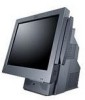
number 11 The IBM SurePOS 500 Series Models 545 and 565 (machine type 4846) enable you to provide fast, accurate customer service and to manage your restaurant or store efficiently. You can configure the SurePOS 500 Series systems to support a wide variety of both IBM and non-IBM input/output - IBM 4846-545 | Service Guide - Page 24
15-in TFT (2 bulb) Touch IBM enhanced Infra-red Audio Not available support Expansion Not available PC-Card slot (accommodates PC cards up to 119 mm long.) I/O ports and connectors 7 standard USB (3 display tablet, 4 tower rear) Mouse (rear) Keyboard 545 and 565 Hardware Service Guide - IBM 4846-545 | Service Guide - Page 25
the SurePOS 500 Models 545 and 565 Table 2. E and P Models Model Number Description 4846-E45 System unit Model 545, preloaded with the Windows XP Embedded for Point of Service (WEPOS) 4846-E65 System unit Model 565, preloaded with the Windows XP Embedded for Point of Service (WEPOS) 4846-P45 - IBM 4846-545 | Service Guide - Page 26
, non-keyboard v Cash drawer v Compact A/N POS KEYBOARD v External USB floppy drive v USB antenna cover (accommodates USB antennas up to 32mm X 101 mm; excluding the exposed connector) v Side cover to accommodate PC Card antennas with lengths up to 119 mm 4 Models 545 and 565 Hardware Service Guide - IBM 4846-545 | Service Guide - Page 27
MSR port USB connectors Tablet cable connector Touch cable connector (located behind door) LCD brightness controls (minus - and plus +) Power button Figure 3 on page 6 and Table 5 on page 6 identifies the rear connectors. Chapter 1. Introducing the IBM SurePOS 500 Series Models 545 and 565 5 - IBM 4846-545 | Service Guide - Page 28
J Serial ports (3), non-powered K 12V serial L VGA M Keyboard Icon N Mouse O, P Q Cash drawer connectors (2 each rated 24 V, 25 mA continuous) Ethernet 3A, 3B R Powered 24V rated for 3A continuous S Powered 12V T USB 2.0 ports (4) 6 Models 545 and 565 Hardware Service Guide - IBM 4846-545 | Service Guide - Page 29
2000, XP Windows Embedded Point of Service (WEPOS) Power management via ACPI IBM UPOS Drivers for Windows, Version 1.9.2 or later. (Includes JavaPOS drivers for Windows and OPOS drivers.) Notes: 1. Only DOS full screen mode supported due to touch screen alignment requirements. 2. Windows DBCS - IBM 4846-545 | Service Guide - Page 30
General Restrictions Touch on primary Supported video resolutions in Windows operating system LCD size Available video resolutions for onboard LCD 12 in. 640 x 480, 720 x 480, 800 x 600 15 in. 640 x 480, 720 x 480, 800 x 600, 960 x 540, 1024 x 768 8 Models 545 and 565 Hardware Service Guide - IBM 4846-545 | Service Guide - Page 31
/ store/) for tested devices. Headphone/microphone v IBM or equivalent Yes Notes: 1. Assumes device natively supports hot plugging and can be hot plugged with any operating system. 2. CANPOS MSR option is mutually exclusive for SurePOS 500 Models 545 and 565. 3. Some PCMCIA devices may require - IBM 4846-545 | Service Guide - Page 32
site. Remote management The SurePOS 500 Models 545 and 565 supports remote system management over the network. The following functions are supported: v Selectable startup sequence v Update POST/BIOS from the network v Ethernet v Power up (wake) on LAN 10 Models 545 and 565 Hardware Service Guide - IBM 4846-545 | Service Guide - Page 33
Introducing the SurePOS 500 Models 545 and 565 Compatible products You can use the following products with the SurePOS 500: v 4610 SureMark Single Station Thermal Printer (RS-232 models) v 4610 SureMark Printer v 4820 SurePoint Solution Terminal v IBM point-of-sale USB devices v Original equipment - IBM 4846-545 | Service Guide - Page 34
12 Models 545 and 565 Hardware Service Guide - IBM 4846-545 | Service Guide - Page 35
16 Using the IBM Diagnostics for POS Systems and Peripherals package . . . . 16 Supported memory keys 17 Updating the flash BIOS 17 Power interruption during flash BIOS update procedure 18 Repairing the flash BIOS 18 Diagnosing problems and troubleshooting 19 Researching the Knowledgebase - IBM 4846-545 | Service Guide - Page 36
. For example, enter 8 to change the month to Aug. 2. Touch enter. The correct month appears as text. 3. Using the displayed keyboard, enter the number of the month. For example, enter 8 for option allows advanced functions for PCI configuration data. 14 Models 545 and 565 Hardware Service Guide - IBM 4846-545 | Service Guide - Page 37
default settings, select Load Optimized Settings from the main menu. Clearing the CMOS settings The SurePOS 500 uses battery-backed CMOS memory to store system settings. If the CMOS memory becomes corrupted : CMOS checksum error - defaults loaded Chapter 2. Running diagnostics and troubleshooting 15 - IBM 4846-545 | Service Guide - Page 38
default values are highly recommended. The IBM SurePOS 500 Series Operating System Installation Guide for Models 545 and 565 provides a list of port resources. Using the IBM Diagnostics for POS Systems and Peripherals package Diagnostics for the SurePOS 500 Models 545 and 565 are available on the - IBM 4846-545 | Service Guide - Page 39
upon your system-only tests available for your machine type are displayed. Supported memory keys The following memory keys are supported by the SurePOS 500 Models 545 and 565: IBM USB 2.0 (256 MB) v FRU: 41D9746 v Part number: 22P9228 Go to www.ibm.com for details on this USB key. PNY USB 2.0 (1 GB - IBM 4846-545 | Service Guide - Page 40
is permanently damaged, the system runs normally, but without backup capability for the BIOS, and the POST message appears at each boot up. 18 Models 545 and 565 Hardware Service Guide - IBM 4846-545 | Service Guide - Page 41
Using the IBM Diagnostics for POS Systems and Peripherals package" on page 16 Appendix A, "Field replaceable parts," on page 95. Chapter 3, "Removing and replacing FRUs for the SurePOS 500 Models 545 and 565," on page 25. Researching the Knowledgebase You can determine if a product problem has been - IBM 4846-545 | Service Guide - Page 42
manual for a description of those messages. Troubleshooting symptoms and actions If the SurePOS 500 system fails with no error message or beep code, see Table 11 to find problem the trouble. Table 11. Symptoms and actions If the problem is... IBM Point of Sale Options and I/O Devices Service Guide - IBM 4846-545 | Service Guide - Page 43
service program. 3. Reinstall the touch driver. 4. Replace the front touch bezel assembly. See "Front bezel and LCD assembly - removing and replacing" on page 36. 5. Replace the system board. See "System board - removing and replacing" on page 49. Chapter 2. Running diagnostics and troubleshooting - IBM 4846-545 | Service Guide - Page 44
on them. 4. Run the keyboard test from the diagnostics program. 5. Replace the keyboard. Diskette drive does not work to the system have test instructions. Refer to those instructions when testing those devices. manual for a description of those messages. 22 Models 545 and 565 Hardware Service Guide - IBM 4846-545 | Service Guide - Page 45
at "Restoring the default CMOS settings" on page 15) before replacing a system board to resolve a problem. This practice allows you to determine if a corrupted CMOS is the source of the trouble. A corrupted CMOS can cause unpredictable problems. Chapter 2. Running diagnostics and troubleshooting 23 - IBM 4846-545 | Service Guide - Page 46
24 Models 545 and 565 Hardware Service Guide - IBM 4846-545 | Service Guide - Page 47
SurePOS 500 Models 545 and 565 Pictorial overview 26 Handling static-sensitive devices 28 Modular servicing for all SurePOS 500 Models 545 and 565 models (4846). Some procedures 4846 is located on the lower right, front frame. See Figure 4 on page 11. 3. Switch OFF the power to the SurePOS - IBM 4846-545 | Service Guide - Page 48
and replacing FRUs Pictorial overview The SurePOS 500 Series Models 545 and 565 is designed for modular servicing and installation. Figure 7 on bezel and LCD assembly - removing and touch-cable cover replacing" on page 36 J Removing the front bezel 26 Models 545 and 565 Hardware Service Guide - IBM 4846-545 | Service Guide - Page 49
Removing and replacing FRUs A B C D E F G H I J Note: These pictures represent only some of the common component removals. Figure 7. Pictorial overview Chapter 3. Removing and replacing FRUs for the SurePOS 500 Models 545 and 565 27 - IBM 4846-545 | Service Guide - Page 50
edges or its frame. v Do not touch solder joints, pins, or exposed printed servicing and minimum tools The SurePOS 500 Models 545 and 565 were designed for modular servicing and requires the minimum use of tools. However, some field replacement parts may require a tool. Table 13 lists the part - IBM 4846-545 | Service Guide - Page 51
rear, tower, and side covers. Front (or HDD) cover removal 1. Switch OFF the power to the SurePOS 500. Unplug the power cord from the external power source. 2. Tilt the top of the display tablet reverse these procedures. Chapter 3. Removing and replacing FRUs for the SurePOS 500 Models 545 and 565 29 - IBM 4846-545 | Service Guide - Page 52
Removing and replacing FRUs Rear cover removal 1. Switch OFF the power to the SurePOS 500. Unplug the power cord from the external power source. 2. Facing the rear of the unit. A Figure 9. Removing the rear cover 3. To replace, reverse these procedures. 30 Models 545 and 565 Hardware Service Guide - IBM 4846-545 | Service Guide - Page 53
by sliding the latches ( A in Figure 10) toward the center. v Open the I/O tailgate cover by rotating it downward. Chapter 3. Removing and replacing FRUs for the SurePOS 500 Models 545 and 565 31 - IBM 4846-545 | Service Guide - Page 54
Removing and replacing FRUs Top cover removal 1. Switch OFF the power to the SurePOS 500. Unplug the power cord from the external power source. 2. Remove the rear cover, following the on the other side. 6. To replace, slide the top cover on from the rear. 32 Models 545 and 565 Hardware Service Guide - IBM 4846-545 | Service Guide - Page 55
Removing and replacing FRUs Hinge cover removal 1. Switch OFF the power to the SurePOS 500. Unplug the power cord from the external power source. 2. Remove the display tablet. See E ) will clear holes ( F in Figure 12). Chapter 3. Removing and replacing FRUs for the SurePOS 500 Models 545 and 565 33 - IBM 4846-545 | Service Guide - Page 56
remove the display tablet. A Figure 13. Removing the display tablet 1. Switch OFF the power to the SurePOS 500. Unplug the power cord from the external power source. 2. Tilt the tablet back and loosen off the unit. 6. To replace, reverse these procedures. 34 Models 545 and 565 Hardware Service Guide - IBM 4846-545 | Service Guide - Page 57
cable - removing and replacing 1. Switch OFF the power to the SurePOS 500. Unplug the power cord from the external power source. cable free from the plastic guide in the frame. 12. To replace, reverse these procedures. Chapter 3. Removing and replacing FRUs for the SurePOS 500 Models 545 and 565 35 - IBM 4846-545 | Service Guide - Page 58
are available as FRUs. 1. Switch OFF the power to the SurePOS 500. Unplug the power cord from the external power source. 2. touch card and perpendicular to the unit, while the LOCKED position ( L ) is closer to the touch card and parallel with the unit. 36 Models 545 and 565 Hardware Service Guide - IBM 4846-545 | Service Guide - Page 59
the front bezel or LCD assembly from the front bezel assembly, reverse these procedures and reconnect the touch cable: a. Ensure that the connector lever is in the open position. See Figure 15 on page in Figure 16. Chapter 3. Removing and replacing FRUs for the SurePOS 500 Models 545 and 565 37 - IBM 4846-545 | Service Guide - Page 60
This section describes how to remove the operator card. 1. Switch OFF the power to the SurePOS 500. Unplug the power cord from the external power source. 2. Follow the steps described in and lift out the card. 5. To replace, reverse these procedures. 38 Models 545 and 565 Hardware Service Guide - IBM 4846-545 | Service Guide - Page 61
replacing FRUs Tablet hinge assembly - removing and replacing 1. Switch OFF the power to the SurePOS 500. Unplug the power cord from the external power source. 2. Remove the tablet as replace, reverse these procedures. Chapter 3. Removing and replacing FRUs for the SurePOS 500 Models 545 and 565 39 - IBM 4846-545 | Service Guide - Page 62
not to drop or jar the HDD during assembly. Do not use an impact power driver. Note: The HDD and bracket are available together as one FRU, and are not remove these to remove the HDD. 1. Switch OFF the power to the SurePOS 500. Unplug the power cord from the external power source. 2. As shown in - IBM 4846-545 | Service Guide - Page 63
HDD requires a jumper to be recognized as Drive 0, the correct position is indicated on a label on the HDD. Chapter 3. Removing and replacing FRUs for the SurePOS 500 Models 545 and 565 41 - IBM 4846-545 | Service Guide - Page 64
disk drive fan and bracket - removing and replacing 1. Switch OFF the power to the SurePOS 500. Unplug the power cord from the external power source. 2. Remove the rear cover Disconnect the cable from the fan. 7. To replace, reverse these procedures. 42 Models 545 and 565 Hardware Service Guide - IBM 4846-545 | Service Guide - Page 65
cables - removing and replacing 1. Switch OFF the power to the SurePOS 500. Unplug the power cord from the external power source. cable free from the plastic guide in the frame. 10. To replace, reverse these procedures. Chapter 3. Removing and replacing FRUs for the SurePOS 500 Models 545 and 565 43 - IBM 4846-545 | Service Guide - Page 66
- removing and replacing 1. Switch OFF the power to the SurePOS 500. Unplug the power cord from the external power source. 2. Follow the instructions described in "Rear cover removal" on page 30. B Figure the slots. 5. To replace, reverse these procedures. 44 Models 545 and 565 Hardware Service Guide - IBM 4846-545 | Service Guide - Page 67
Removing and replacing FRUs Power supply - removing and replacing 1. Switch OFF the power to the SurePOS 500. Unplug the power cord from the external power source. 2. Remove the back cover as align with the screw hole. Chapter 3. Removing and replacing FRUs for the SurePOS 500 Models 545 and 565 45 - IBM 4846-545 | Service Guide - Page 68
" on page 30. 3. Follow the instructions described in "Power supply - removing and replacing" on page 45 H Figure 24. Removing the power supply latch arm 4. Remove screws ( H ) and then lift off the power supply. 5. To replace, reverse these procedures. 46 Models 545 and 565 Hardware Service Guide - IBM 4846-545 | Service Guide - Page 69
Rear connector panel (tailgate) - removing and replacing 1. Switch OFF the power to the SurePOS 500. Unplug the power cord from the external power source. 2. Remove the rear cover cover by rotating it downward. Chapter 3. Removing and replacing FRUs for the SurePOS 500 Models 545 and 565 47 - IBM 4846-545 | Service Guide - Page 70
from the system board. 8. To replace, reverse these procedures, being sure to align the metal tabs on the side of the tailgate with the plastic guides on the frame. 48 Models 545 and 565 Hardware Service Guide - IBM 4846-545 | Service Guide - Page 71
touching this unit. See "Electrostatic Discharge (ESD)" on page 130. Note: The system board assembly comes with a tray and top cover. Figure 27. Removing the system board 1. Switch OFF the power to the SurePOS Figure 27. Chapter 3. Removing and replacing FRUs for the SurePOS 500 Models 545 and 565 49 - IBM 4846-545 | Service Guide - Page 72
assembly on a table and remove the following parts: v Memory modules - See "Memory modules page 61. v Optional integrated VFD Install these parts on the new system board. The new system board VPD). a. Boot using the memory key. b. Choose POS System Test. c. Choose Utilities. d. Choose Vital Product - IBM 4846-545 | Service Guide - Page 73
corner in the silkscreen. System-board battery - removing and replacing 1. Switch OFF the power to the SurePOS 500. Unplug the power cord from the external power source. 2. Remove the rear cover as described at page 47 Chapter 3. Removing and replacing FRUs for the SurePOS 500 Models 545 and 565 51 - IBM 4846-545 | Service Guide - Page 74
Removing and replacing FRUs L Figure 29. System-board battery 5. Remove the old battery from the slot L as shown in Figure 29. 6. Facing the rear of the machine, insert the new battery with the positive side to the left 52 Models 545 and 565 Hardware Service Guide - IBM 4846-545 | Service Guide - Page 75
FRUs Processor fan/heatsink assembly - removing and replacing 1. Switch OFF the power to the SurePOS 500. Unplug the power cord from the external power source. 2. Remove the rear cover heatsink or with a new processor. Chapter 3. Removing and replacing FRUs for the SurePOS 500 Models 545 and 565 53 - IBM 4846-545 | Service Guide - Page 76
the processor. Attention: Establish personal grounding before touching this unit. See "Electrostatic Discharge (ESD)" on SurePOS Models 545 and 565 contain a LGA 775 CPU socket. This socket contains very finely pitched pins. You must take care when servicing 545 and 565 Hardware Service Guide - IBM 4846-545 | Service Guide - Page 77
and replacing FRUs Memory modules - removing and replacing Attention: Establish personal grounding before touching this unit. For more information, see "Electrostatic Discharge (ESD)" on page 130 . See A in Figure 31. Chapter 3. Removing and replacing FRUs for the SurePOS 500 Models 545 and 565 55 - IBM 4846-545 | Service Guide - Page 78
545 and 565. Although advertised as industry standard, all memory does not work with every product, IBM performs extensive life and reliability testing to insure that memory offered by IBM will operate correctly over all voltage and temperature ranges. 56 Models 545 and 565 Hardware Service Guide - IBM 4846-545 | Service Guide - Page 79
and replacing FRUs Base plate - removing and replacing 1. Switch OFF the power to the SurePOS 500. Unplug the power cord from the external power source. 2. Remove the rear cover as . S Figure 33. Removing the base plate Chapter 3. Removing and replacing FRUs for the SurePOS 500 Models 545 and 565 57 - IBM 4846-545 | Service Guide - Page 80
and replacing 1. Switch OFF the power to the SurePOS 500. Unplug the power cord from the external power the slot to either the RS-232 or keyboard position, depending on the configuration of the MSR MSR operates correctly. See "Using the IBM Diagnostics for POS Systems and Peripherals package" on page - IBM 4846-545 | Service Guide - Page 81
. Removing the PC card adapter slot blank PC card - removing and replacing 1. Switch OFF the power to the SurePOS 500. Unplug the power cord from the external power source. 2. Remove the front cover. See "Front (or card. Chapter 3. Removing and replacing FRUs for the SurePOS 500 Models 545 and 565 59 - IBM 4846-545 | Service Guide - Page 82
IBM recommends that you stop the PC card in Windows before you physically remove it. After installation, run the diagnostics to ensure that the PC card operates correctly. See "Using the IBM Diagnostics for POS Systems and Peripherals package" on page 16. 60 Models 545 and 565 Hardware Service Guide - IBM 4846-545 | Service Guide - Page 83
To replace, reverse these procedures. After installation, run the diagnostics to ensure that the video adapter card operates correctly. See "Using the IBM Diagnostics for POS Systems and Peripherals package" on page 16. Chapter 3. Removing and replacing FRUs for the SurePOS 500 Models 545 and 565 61 - IBM 4846-545 | Service Guide - Page 84
Removing and replacing FRUs Speaker - removing and replacing 1. Switch OFF the power to the SurePOS 500. Unplug the power cord from the external power source. 2. Remove the front cover 3. Loosen the speaker cover thumbscrew as shown in J in Figure 38. 62 Models 545 and 565 Hardware Service Guide - IBM 4846-545 | Service Guide - Page 85
speaker hooks must fit into the hooks on the frame, or the HDD cover will not close properly. Chapter 3. Removing and replacing FRUs for the SurePOS 500 Models 545 and 565 63 - IBM 4846-545 | Service Guide - Page 86
customer display - removing and replacing 1. Switch OFF the power to the SurePOS 500. Unplug the power cord from the external power source. 2. Remove operates correctly. See "Using the IBM Diagnostics for POS Systems and Peripherals package" on page 16. 64 Models 545 and 565 Hardware Service Guide - IBM 4846-545 | Service Guide - Page 87
Chapter 4. Mounting the SurePOS 500 Models 545 and 565 Mounting the base plate on a countertop 67 Non-keyboard-integration tray mounting 70 Countertop with non-keyboard-integration tray mounting 70 Installing filler panels without a printer 75 Cash drawer 75 Keyboard-integration tray 80 - IBM 4846-545 | Service Guide - Page 88
(continued) To mount to a countertop using the non-keyboard-integration tray, see "Countertop with non-keyboard-integration tray mounting" on page 70. To mount on a cash drawer using the non-keyboard-integration tray, see "Cash drawer" on page 75. 66 Models 545 and 565 Hardware Service Guide - IBM 4846-545 | Service Guide - Page 89
or cash drawer using the keyboard-integration tray, see "Countertop and full-size cash drawer" on page 80 Before mounting your system, first install any internal and external devices on the unit. Mounting the base plate on a countertop You can mount the SurePOS 500 Models 545 and 565 free-standing - IBM 4846-545 | Service Guide - Page 90
Mounting the Models 545 and 565 (2x) 07.2 166 18 (2x) 3 (2x) 211.7 25 (2x) 8.8mm (2x) 07.2 18 133 173.7 13.85 35 19.15 Figure 41 on top of the counter, route all cables out the rear of the system. Lay the cables flat along the countertop. 68 Models 545 and 565 Hardware Service Guide - IBM 4846-545 | Service Guide - Page 91
to the SurePOS 500 and verify that the system is operating correctly by checking the indicator lights (LEDs) on the front of the touch screen. 12. Install your software. Refer to IBM SurePOS Model 545 and 565 Operating System Installation Guide. Chapter 4. Mounting the SurePOS 500 Models 545 and 565 - IBM 4846-545 | Service Guide - Page 92
full-size cash drawer" on page 80. Countertop with non-keyboard-integration tray mounting Figure 43. Countertop with non-keyboard-integration tray mounting The countertop integration tray can be used as and cutout dimensions, see Figure 44 on page 71. 70 Models 545 and 565 Hardware Service Guide - IBM 4846-545 | Service Guide - Page 93
Mounting the Models 545 and 565 441.52 mm (17.38 in.) 90 mm (3.54 in.) 149 mm (5.87 in.) 128 mm (5.04 in.) 66.22 mm (2.6 in 25 in.) until the plastic fence is detached from the metal integration tray A , as shown in Figure 46 on page 72. Chapter 4. Mounting the SurePOS 500 Models 545 and 565 71 - IBM 4846-545 | Service Guide - Page 94
Mounting the Models 545 and 565 B A Figure 46. Sliding the fence off of the integration tray b. Drill the four mounting holes and cut a hole in provided with the kit. Use 60-mm (0.25-in.), pan-head screws. e. Reattach the fence to the integration tray. 72 Models 545 and 565 Hardware Service Guide - IBM 4846-545 | Service Guide - Page 95
Mounting the Models 545 and 565 J C K B F A K D I E H L G Figure 47. Overview of integration tray, SurePOS 500, printer, and filler panels Table 16. Countertop integration tray legend A Fence G B SurePOS 500 H C Mounting plate I D 4610 SureMark Printer J E Mounting plate for - IBM 4846-545 | Service Guide - Page 96
IBM 4610 SureMark Printer on the integration tray. Go to "Installing IBM 4610 SureMark Models TF6 or TF7 printers" on page 91 for detailed instructions AC power cord into an AC outlet. 12. Replace the SurePOS 500 rear cover. 13. Install the filler panels after you 545 and 565 Hardware Service Guide - IBM 4846-545 | Service Guide - Page 97
operating correctly by checking the indicator lights (LEDs) on the front of the touch screen. 17. Install your software. Refer to IBM SurePOS Model 545 and 565 Operating System Installation Guide. Installing filler panels without a printer For systems without a printer: 1. Install the mounting plate - IBM 4846-545 | Service Guide - Page 98
SureMark printer on the integration tray with the SurePOS 500. Go to "Installing IBM 4610 SureMark Models TF6 or TF7 printers" on page 91 for detailed instructions on printer cable routing, RS-232 printer switch settings, and mounting plate installation: 76 Models 545 and 565 Hardware Service Guide - IBM 4846-545 | Service Guide - Page 99
the data cable, under the cable tie bar and toward the rear connector panel as shown in Figure 65 on page 93. b. Attach the SurePOS 500 Models 545 and 565 base mounting plate A to the right side of the integration tray. Slide the front of the plate under the appropriate pair of - IBM 4846-545 | Service Guide - Page 100
Mounting the Models 545 and 565 7. Route all cables through the hole at the center rear of the cash drawer. Then route the cables through the Tilt the modesty cover C so the front hooks attach to the tray; then push down until the cover snaps into place. 78 Models 545 and 565 Hardware Service Guide - IBM 4846-545 | Service Guide - Page 101
power to the SurePOS 500. Verify that the system is operating correctly by checking the indicator lights (LEDs) on the front of the system. 19. Install your software. Refer to IBM SurePOS Model 545 and 565 Operating System Installation Guide. Chapter 4. Mounting the SurePOS 500 Models 545 and 565 79 - IBM 4846-545 | Service Guide - Page 102
keyboard are mounted the same way when the full-size keyboard-integration tray is used for a countertop or cash drawer mount. Therefore, the instructions . 1. Prepare the SurePOS 500 to mount to the keyboard-integration tray: a. Remove the rear cover. 80 Models 545 and 565 Hardware Service Guide - IBM 4846-545 | Service Guide - Page 103
of the integration tray. See Figure 54 on page 82 for location of feet. d. Attach the keyboard-integration tray to the countertop using four mounting screws, one at each corner of tray. The four mounting to the tray with the six small screws. Chapter 4. Mounting the SurePOS 500 Models 545 and 565 81 - IBM 4846-545 | Service Guide - Page 104
Models 545 and 565 E D C B A Figure 54. Countertop keyboard-integration tray assembly Table 17. Countertop integration tray legend A Four rubber feet D B Keyboard-integration tray E C Insulator plate Mounting plate Fence 4. Prepare the SurePOS 500 to mount to the keyboard-integration - IBM 4846-545 | Service Guide - Page 105
545 and 565 5. Remove the rear cover on the cash drawer. While pressing in on the two buttons located on the sides of the cash drawer, pull back on the rear cover back to remove it. Discard this rear cover. A new rear cover is used for installation of the keyboard 10. Attach the SurePOS 500 to the - IBM 4846-545 | Service Guide - Page 106
tray 11. Install the IBM 4610 SureMark printer on the integration tray, by performing the following steps: Note: See the 4610 SureMark Point-of-Sale Printers User's Guide for detailed information about switch settings and cabling for the printer. 84 Models 545 and 565 Hardware Service Guide - IBM 4846-545 | Service Guide - Page 107
printer base. v For the large-footprint 4610 SureMark Model TG3 and TG4 printers, place the printer directly onto the integration tray. 12. To install the keyboard, perform the following steps. See Figure 58 on page 86 for callout locations: Chapter 4. Mounting the SurePOS 500 Models 545 and 565 85 - IBM 4846-545 | Service Guide - Page 108
545 and 565 Figure 58. Installing the keyboard onto the integration tray a. Attach the keyboard cable A to the IBM PS/2® port on the rear connector panel. b. Place the keyboard on the integration tray while pushing the excess keyboard the following steps: 86 Models 545 and 565 Hardware Service Guide - IBM 4846-545 | Service Guide - Page 109
AC power cord to the power supply. 16. Connect the peripheral cables to the appropriate ports on the SurePOS 500 rear connector panel. Make the connections on the bottom row of the panel first and work upward. cover to power on the printer. Chapter 4. Mounting the SurePOS 500 Models 545 and 565 87 - IBM 4846-545 | Service Guide - Page 110
565 22. Switch ON the power and verify that the system is operating correctly by checking the indicator lights (LEDs) on the front of the touch screen. 23. Install your software. Refer to IBM SurePOS Model 545 and 565 Operating System Installation Guide. 88 Models 545 and 565 Hardware Service Guide - IBM 4846-545 | Service Guide - Page 111
instructions to mount a character display to a cash drawer. 1. Prepare the system for installation of the distributed customer display. a. Switch OFF the power at the system unit. b. Remove the SurePOS 500 Models 545 for a non-keyboard integration tray or keyboard integration tray to complete - IBM 4846-545 | Service Guide - Page 112
the Models 545 and 565 4. To install a distributed customer display D on a non-keyboard integration tray, Plug it into the 15-pin serial connector. e. Reinstall the rear cover of the SurePOS 500 Model 514 (see "Rear cover removal" on page 30). f. Reinstall the 545 and 565 Hardware Service Guide - IBM 4846-545 | Service Guide - Page 113
TF7 printers Note: Service for the IBM SurePOS Model 4951, Model 514 includes the IBM 4610 SureMark printer. The IBM 4610 SureMark Model TF6 and TF7 (4610 TF6 or TF7) are the smaller 4610 models that contain only a thermal customer receipt station. These models do not support document printing. For - IBM 4846-545 | Service Guide - Page 114
Figure 64 for switch location. For switch settings, see the IBM 4610 SureMark Point-of-Sale Printers User's Guide. 4. Connect and route the RS-232 communication cable or Powered USB cable A and the power supply cable B as shown in Figure 65 on page 93. 92 Models 545 and 565 Hardware Service Guide - IBM 4846-545 | Service Guide - Page 115
tray b. The procedure for mounting the printer to a non-keyboard integration tray is the same for countertop or cash drawer. With the mounting plate attached to the printer, slide the front of the printer mounting plate into the slots located Chapter 4. Mounting the SurePOS 500 Models 545 and 565 93 - IBM 4846-545 | Service Guide - Page 116
Mounting the Models 545 and 565 toward the front of the integration tray. Secure the printer by tightening the two thumbscrews on the mounting screws to enable correct installation of the filler panels. A B Figure 67. 4610 TF6 or TF7 cable routing 94 Models 545 and 565 Hardware Service Guide - IBM 4846-545 | Service Guide - Page 117
panels. . . . 102 Assembly 5: Cash drawer non-keyboard integration tray and filler panels 104 This chapter contains field-replaceable part number information the SurePOS 500 Models 545 and 565. How to use the FRU catalog This parts listing contains reference drawings and a corresponding index - IBM 4846-545 | Service Guide - Page 118
Field-replaceable parts Assembly 1: Models 545 and 565 1 2 3 4 5 6 7 8 9 10 11 12 13 14 15 16 17 18 19 20 21 22 23 24 25 26 27 28 96 Models 545 and 565 Hardware Service Guide - IBM 4846-545 | Service Guide - Page 119
22 -23 -24 - -25 -26 -27 - -28 - - - - - Part Number 42V3886 42V3887 12X1000 12X1001 42V3889 42V3890 42V3897 42V3893 42V3894 42V3892 12X1036 42V3924 41D0171 42V3937 42V3925 , 12 in. LCD assembly, 15 in. MSR hole plug Touch cable door, 12 in. Touch cable door, 15 in. Operator card kit, 12 in. - IBM 4846-545 | Service Guide - Page 120
Field-replaceable parts Assembly 2: Countertop and cash drawer keyboard integration tray and filler panels 98 Models 545 and 565 Hardware Service Guide - IBM 4846-545 | Service Guide - Page 121
Assembly 2: (continued) Asm- Index 2- -1 - - - - - -2 - - - - -3 - - - - -4 Part Number 41D0214 42V3964 42V3965 47P9273 41D0216 14R0157 Units Description Countertop and cash drawer keyboard integration tray and filler panels 1 FRU, plate/fence ASM, wide cash drawer or countertop (includes - IBM 4846-545 | Service Guide - Page 122
Field-replaceable parts Assembly 3: Optional peripherals 4 3 2 1 100 Models 545 and 565 Hardware Service Guide - IBM 4846-545 | Service Guide - Page 123
Asm- Index 3-1 -1 -2 -3 -4 Part Number 42V3960 42V3961 42N5755 42V3958 42V3959 Units Description MSR, 3-track MSR, JUCC Speaker Display, integrated 2x20 VFD housing, integrated Assembly 3: (continued) Appendix A. Field replaceable parts 101 - IBM 4846-545 | Service Guide - Page 124
Field-replaceable parts Assembly 4: Countertop non-keyboard integration tray and filler panels 4 3 1 6 5 6 4 2 4 4 102 Models 545 and 565 Hardware Service Guide - IBM 4846-545 | Service Guide - Page 125
Assembly 4: (continued) Asm- Index 4- -1 -2 -3 -4 -5 -6 - Part Number 41D0261 41D0211 42V3966 42V3967 12X1129 41D0212 - - Units Description Countertop non-keyboard integration tray and filler panels Plate/fence assembly, counter top mounting Plate assembly, printer mounting Plate assembly, - IBM 4846-545 | Service Guide - Page 126
Field-replaceable parts Assembly 5: Cash drawer non-keyboard integration tray and filler panels 3 4 2 1 4 6 104 Models 545 and 565 Hardware Service Guide 6 5 4 - IBM 4846-545 | Service Guide - Page 127
Assembly 5: (continued) Asm- Index 5- -1 -2 -3 -4 -5 -6 - - - Part Number 41D0210 41D0211 42V3966 42V3967 20P0308 12X1129 41P0212 Units Description Cash drawer non-keyboard integration tray and filler panels 1 Plate and fence, cash drawer mount 1 Plate, printer mounting 1 Plate, terminal mounting - IBM 4846-545 | Service Guide - Page 128
106 Models 545 and 565 Hardware Service Guide - IBM 4846-545 | Service Guide - Page 129
Appendix B. Power cords Table 19. Power cord lengths and part numbers by country Part number Length Country 39M5066 4.3 m Argentina 39M5093 4.3 m (non-locking) United States 39M5077 1.8 m United States, Chicago 39M5107 4.3 m (locking) United States © Copyright IBM Corp. 2006 107 - IBM 4846-545 | Service Guide - Page 130
Power cords 108 Models 545 and 565 Hardware Service Guide - IBM 4846-545 | Service Guide - Page 131
connectors 116 Speaker connector 116 MSR connector 116 USB port connectors 118 Keyboard connector 118 Mouse connector 119 Microphone connector 119 Headphone connector 119 This appendix provides information on power subsystems, and environmental requirements. © Copyright IBM Corp. 2006 109 - IBM 4846-545 | Service Guide - Page 132
are described in Table 20. Table 20. Height, weight and depth of the SurePOS 500 Models 545 and 565 4846 Weight Height: Tablet Height at 15 degrees maximum Depth: Tablet Depth: Tablet at 15 in) Retail tray 551.1 mm (21.7 in.) 519.7 mm (20.5 in.) 110 Models 545 and 565 Hardware Service Guide - IBM 4846-545 | Service Guide - Page 133
(17.7 in.) 491.5mm (19.3 in.) 43.9mm (1.7 in.) 7.2mm (.28 in.) 449.5mm (17.7 in.) B 523.9mm (20.6 in.) Figure 68. Dimensions of SurePOS Models 545 and 565 with retail tray. The tablet is shown at 15 degrees. 39.6mm (1.5 in) A 31.2mm (1.2 in.) 346.6mm (13.6 in) 43.9mm (1.7 in - IBM 4846-545 | Service Guide - Page 134
.) 415.4mm (17.7 in.) 457.65mm (18.0 in.) System specifications and planning information 43.9mm (1.7 in.) 3.4mm (.13 in.) 449.5mm (17.7 in.) B Figure 70. SurePOS Models 545 and 565 with cash drawer tray. The tablet is shown at 15 degrees. 112 Models 545 and 565 Hardware Service Guide - IBM 4846-545 | Service Guide - Page 135
System specifications and planning information Dimensions of unit with 12-inch display 201.6mm (7.94 in.) 212mm (8.35 in.) 357.9mm (14.09 in.) 31.2mm (31.2 in.) 322.1mm (12.68 in.) 362mm (14.25 in.) 389.1mm (15.32) 212mm (8.35 in.) 242.3mm (9.54 in.) 307.9mm (12.1 in.) 15° 351.8mm (13.9 in.) - IBM 4846-545 | Service Guide - Page 136
.) Figure 72. Dimensions of unit with 15-inch display 228.2mm (8.98 in.) 15° 247.6mm (9.75 in.) 324.4mm (12.77 in.) 114 Models 545 and 565 Hardware Service Guide - IBM 4846-545 | Service Guide - Page 137
- 240 V AC 50 or 60 Hz 50 or 60 Hz Frequency Table 24. SurePOS 500 Series Models 545 and 565 power supply Nominal output voltage Tolerance Rated Current +5.0 V AUX ±5% 2.0 of powered USB devices, especially printers, is not supported. Some powered USB devices create surge currents that may - IBM 4846-545 | Service Guide - Page 138
Keyboard and Mouse 5V Maximum current 0.95A 0.65A 0.5 A 0.5 A 1.5 A 3.0 A continuous 5.0 A peak 0.6 A Connector-pin assignments This following sections list connector-pin assignments Pin 1 2 3 4 116 Models 545 and 565 Hardware Service Guide Connector +5 V dc Serial data out Serial data in Ground - IBM 4846-545 | Service Guide - Page 139
Connector-pin assignments Table 28. MSR connector-pin assignments (continued) Pin Connector 5 KBD enable 6 Keyboard data 7 Keyboard clock 8 Ground Appendix C. System specifications and planning information 117 - IBM 4846-545 | Service Guide - Page 140
. USB port connector-pin assignments Powered USB Pin Shell Connector Shield 1 5 V Vbus 2 −Data 3 +Data 4 Ground 5 Ground 6 Vplus (12 V or 24 V) 7 Vplus (12 V or 24 V) 8 Ground Keyboard connector 6 4 2 118 Models 545 and 565 Hardware Service Guide 5 3 1 - IBM 4846-545 | Service Guide - Page 141
mouse connector-pin assignments Pin Signal I/O Pin Signal I/O 1 Keyboard data I/O 4 +5 V Main I/O 3 Ground 5 Keyboard clock Mouse connector 6 5 4 3 2 1 Table 32. Keyboard and mouse connector-pin assignments Pin Signal I/O Pin Signal I/O 2 Mouse data I/O 4 +5 V Main - IBM 4846-545 | Service Guide - Page 142
connectors RJ-45 Connectors (3): 8 1 Table 35. RJ-45 connector-pin assignments Pin Signal Pin 1 DSR 5 2 CD 6 3 DTR 7 4 Ground 8 Signal RXD TXD CTS RTS 120 Models 545 and 565 Hardware Service Guide - IBM 4846-545 | Service Guide - Page 143
Connector-pin assignments 15-pin serial connector: The 15-pin serial connector is a female connector. 8 1 15 9 Table 36. Assignments for 15-pin serial connector Pin Connector Pin 1 Carrier detect 8, 9 2 3 4 5 6 7, 10 Receive data 11 Transmit data 12 Data terminal ready 13 Ground - IBM 4846-545 | Service Guide - Page 144
13 6 Red ground 14 7 Green ground 15 8 Blue ground Connector No connection Ground No connection Monitor ID1 Horizontal sync Vertical sync Monitor ID3 122 Models 545 and 565 Hardware Service Guide - IBM 4846-545 | Service Guide - Page 145
Cash drawer connector (2) Connector-pin assignments 41 Table 39. Assignment of cash drawer connector pins Pin Connector 1 Ground 2 Sensor 3 Open signal 4 +24 V dc Integrated customer display connector To access this connector, you must remove the rear cover. 1 4 Table 40. Assignment - IBM 4846-545 | Service Guide - Page 146
0 to 60° C. 5 to 100% Maximum wet bulb temperature 27° C. 27° C. 29° C. This product is designed to operate up to 3050 m (10,000 ft.). 124 Models 545 and 565 Hardware Service Guide - IBM 4846-545 | Service Guide - Page 147
to evaluate and verify the operation of any non-IBM product, program, or service. IBM may have patents or pending patent applications covering the are not part of the materials for this IBM product and use of those Web sites is at your own risk. Information concerning non-IBM products was - IBM 4846-545 | Service Guide - Page 148
. Questions on the capabilities of non-IBM products should be addressed to the suppliers of those products. This information is for planning purposes only. The information herein is subject to change before the products described become available. 126 Models 545 and 565 Hardware Service Guide - IBM 4846-545 | Service Guide - Page 149
for a Class A digital device, pursuant to Part 15 of the FCC Rules. These limits are installed and used in accordance with the instruction manual, may cause harmful interference to radio communications used in order to meet FCC emission limits. IBM is not responsible for any radio or television - IBM 4846-545 | Service Guide - Page 150
vergröβern.″ Anmerkung: Um die Einhaltung des EMVG sicherzustellen sind die Geräte, wie in den IBM Handbüchern angegeben, zu installieren und zu betreiben. Australia / New Zealand Attention: This is a the user may be required to take adequate measures. 128 Models 545 and 565 Hardware Service Guide - IBM 4846-545 | Service Guide - Page 151
Korean Communications Statement Please note that this device has been approved for business purposes with regard to electromagnetic interference. If you find this is not suitable for your use, you may exchange it for a non-business purpose one. Chinese Class A warning statement Attention: This is a - IBM 4846-545 | Service Guide - Page 152
SurePOS Wake on LAN Microsoft, Windows, Windows NT, and the Windows logo are trademarks of Microsoft Corporation in the United States, other countries, or both. Celeron and Intel are trademarks of Intel corporation in the United States, or other countries. 130 Models 545 and 565 Hardware Service - IBM 4846-545 | Service Guide - Page 153
Java and all Java-based trademarks and logos are trademarks or registered trademarks of Sun Microsystems, Inc. in the United States, or other countries, or both. Other company, product, or service names may be trademarks or service marks of others. Appendix D. Notices 131 - IBM 4846-545 | Service Guide - Page 154
132 Models 545 and 565 Hardware Service Guide - IBM 4846-545 | Service Guide - Page 155
Appendix E. Safety information Before you begin to install or service this product, read the following safety information. Safety Information- or disconnect signal cables to prevent a possible shock from touching two surfaces with different electrical potentials. © Copyright IBM Corp. 2006 133 - IBM 4846-545 | Service Guide - Page 156
F), solder directly to the cell, incinerate, or expose the cell contents to water. Keep away from children. Replace only with the part number specified for this IBM product. Use of a different battery may present a risk of fire or explosion. The battery connector is polarized; do not attempt to - IBM 4846-545 | Service Guide - Page 157
Safety Information-Arabic Safety information Appendix E. Safety information 135 - IBM 4846-545 | Service Guide - Page 158
Safety information 136 Models 545 and 565 Hardware Service Guide - IBM 4846-545 | Service Guide - Page 159
Safety Information-Brazilian Portuguese Safety information Appendix E. Safety information 137 - IBM 4846-545 | Service Guide - Page 160
do da célula à água. Mantenha longe do alcance de crianças. Substitua apenas pelo número de peça especificado para este produto IBM. A utilização de uma bateria diferente representa risco de incêndio ou explosão. O conector da bateria é polarizado; não tente reverter a polaridade. Descarte a bateria - IBM 4846-545 | Service Guide - Page 161
Safety Information-French Safety information Appendix E. Safety information 139 - IBM 4846-545 | Service Guide - Page 162
e. même référence. Toute autre pile risquerait de prendre feu ou d'exploser. Le connecteur de la pile est polarisé. N'essayez pas d'inverser la polarité. 140 Models 545 and 565 Hardware Service Guide - IBM 4846-545 | Service Guide - Page 163
Safety information Pour le recyclage ou la mise au rebut, reportez-vous à. la ré.glementation en vigueur. Appendix E. Safety information 141 - IBM 4846-545 | Service Guide - Page 164
Safety information Safety Information-Hebrew 142 Models 545 and 565 Hardware Service Guide - IBM 4846-545 | Service Guide - Page 165
Safety information Appendix E. Safety information 143 - IBM 4846-545 | Service Guide - Page 166
Safety information Safety Information-Korean 144 Models 545 and 565 Hardware Service Guide - IBM 4846-545 | Service Guide - Page 167
Safety information Note: In the UK, by law, the telephone cable must be connected after the power cord. Note: In the UK, by law, the power cord must be disconnected after the telephone line cable. Appendix E. Safety information 145 - IBM 4846-545 | Service Guide - Page 168
Safety information 146 Models 545 and 565 Hardware Service Guide - IBM 4846-545 | Service Guide - Page 169
Safety Information-Italian Safety information Appendix E. Safety information 147 - IBM 4846-545 | Service Guide - Page 170
una batteria contrassegnata dal numero parte specifico per questo prodotto IBM. L'utilizzo di un altro tipo di batteria può determinare rischi di incendio o di esplosione. Il connettore della batteria è polarizzata; non tentare di invertire la polarità. 148 Models 545 and 565 Hardware Service Guide - IBM 4846-545 | Service Guide - Page 171
Safety information Smaltire la batteria secondo la normativa in vigore (D.Lgs. 22 del 5/2/97) e successive disposizioni nazionali e disposizioni locali. Appendix E. Safety information 149 - IBM 4846-545 | Service Guide - Page 172
Safety information Safety Information-Spanish 150 Models 545 and 565 Hardware Service Guide - IBM 4846-545 | Service Guide - Page 173
contenido de la pila. Manténgala alejada de los niños. Sustitúyala sólo con el número de pieza que se especifica para este producto IBM. El uso de una batería distinta puede causar riesgos de incendio o explosión. El conector de batería está polarizado; no intente invertir la polaridad. Deseche la - IBM 4846-545 | Service Guide - Page 174
oder lösen, um gefährliche Körperströme zu vermeiden, die bei Berühren zweier Flächen mit möglicherweise unterschiedlichen elektrischen Potentialen auftreten können. 152 Models 545 and 565 Hardware Service Guide - IBM 4846-545 | Service Guide - Page 175
ührung bringen. Batterie nicht in Reichweite von Kindern aufbewahren. Eine verbrauchte Batterie nur durch eine Batterie mit der für dieses IBM Produkt spezifizierten Teilenummer ersetzen. Andere Batterien können sich entzünden oder explodieren. Der Batterieanschluß hat zwei verschiedene Pole; beim - IBM 4846-545 | Service Guide - Page 176
Safety information Safety Information-Traditional Chinese 154 Models 545 and 565 Hardware Service Guide - IBM 4846-545 | Service Guide - Page 177
Safety information Appendix E. Safety information 155 - IBM 4846-545 | Service Guide - Page 178
Safety information 156 Models 545 and 565 Hardware Service Guide - IBM 4846-545 | Service Guide - Page 179
installing 91 A about this guide xix accessibility of publications xx troubleshooting 20 Cash drawer connector pin assignments 123 cash drawer, countertop and full-size 80 checklist, problem pin assignments 123 keyboard pin assignments full-size cash 80 Driver for Windows, IBM UPOS 7 dual video - IBM 4846-545 | Service Guide - Page 180
replaceable parts 95 IBM UPOS Drivers troubleshooting 22 keyboard-integration tray mounting 80 L Load defaults 15 158 Models 545 and 565 Hardware Service Guide M magnetic stripe reader connector pin assignments 116 main window, configuration 13 management features, system 9 memory keys, supported - IBM 4846-545 | Service Guide - Page 181
FRUs 25 requirements power 115 resolutions and operating systems, understanding the supported video 7 restoring default CMOS settings 15 restrictions, display 7 RJ-45 connector pin assignments 120 running diagnostics and troubleshooting 13 S safety laser xi notice translations xi notices xi safety - IBM 4846-545 | Service Guide - Page 182
21 touch screen, tapping twice 13 trademarks 130 troubleshooting 20 preliminary checklist 19 U understanding the supported video resolutions and operating systems 7 universal serial bus (USB) connector pin assignments 118 update flash BIOS 17 UPOS Drivers for Windows, IBM 7 URL, support 16 - IBM 4846-545 | Service Guide - Page 183
. (1) The assignment of addresses to the instructions of a program. (2) In data communication, is to send data. © Copyright IBM Corp. 2006 alphanumeric. Pertaining to services, functions, and protocols. See network architecture. attach. (1) To connect a device physically. (2) To make a device a part - IBM 4846-545 | Service Guide - Page 184
part of a network other than an attaching device, such as an IBM 8228 Multistation Access Unit. (2) Hardware or software that is part representation of facts, concepts, or instructions in a formalized manner suitable , that 162 Models 545 and 565 Hardware Service Guide performs input, processing, - IBM 4846-545 | Service Guide - Page 185
driver. A software component that controls a device. dump. (1) To record, at a particular instant, the contents of all or part Communications Commission. feature. A part of an IBM product that may be ordered communicate with a computer. Examples are a keyboard or a mouse. hot plugging. Process - IBM 4846-545 | Service Guide - Page 186
two to the tenth power, or 1024. keyboard. A group of numeric keys, alphabetic when activated. 164 Models 545 and 565 Hardware Service Guide line. On a terminal, the part of a program, in some cases a single instruction or link stations. (3) In the IBM Store System, the logical link providing - IBM 4846-545 | Service Guide - Page 187
Program-addressable storage from which instructions and other data can be provide services that can be selected or enabled as part of a configuration process. (3) A piece unit, a display, a keyboard, one or more diskette drives include the various models of the IBM Personal Computers. plug. (1) A - IBM 4846-545 | Service Guide - Page 188
board. In a system unit, the main circuit board that supports a variety of basic system devices, such as a keyboard or a mouse, and provides other basic system functions. system bus. The unit that connects the CPU to the main memory on the motherboard. 166 Models 545 and 565 Hardware Service Guide - IBM 4846-545 | Service Guide - Page 189
It may have one or more disk or diskette drives. (3) In an IBM Store System terminal, the part of the terminal that contains the processing unit, ROM, RAM, disk conductors twisted together. (A) typematic. The ability of a key on a keyboard to repeatedly type a character as long as it is held down. - IBM 4846-545 | Service Guide - Page 190
168 Models 545 and 565 Hardware Service Guide - IBM 4846-545 | Service Guide - Page 191
number index Part Number 12X1000 12X1001 12X1009 12X1036 12X1110 12X1129 12X1129 14R0157 97 97 97 97 97 97 97 97 97 97 97 97 97 97 97 © Copyright IBM Corp. 2006 Part Number 42V3948 42V3949 42V3950 42V3951 42V3952 42V3953 42V3956 42V3957 42V3958 42V3959 42V3960 42V3961 42V3964 42V3965 42V3966 - IBM 4846-545 | Service Guide - Page 192
170 Models 545 and 565 Hardware Service Guide - IBM 4846-545 | Service Guide - Page 193
would like to hear from you SurePOS 500 Series Hardware Service Guide for Models 545 and 565 Publication No. SY27-0423 responses. May we contact you? h Yes h No When you send comments to IBM, you grant IBM a nonexclusive right to use or distribute your comments in any way it believes appropriate - IBM 4846-545 | Service Guide - Page 194
BUSINESS REPLY MAIL FIRST-CLASS MAIL PERMIT NO. 40 ARMONK, NEW YORK POSTAGE WILL BE PAID BY ADDRESSEE IBM Corporation Retail Store Solutions Information Development Department ZBDA IBM Corporation P.O. Box 12195 Research Triangle Park, NC 27709-9990 Fold and Tape Please do not staple Fold and - IBM 4846-545 | Service Guide - Page 195
- IBM 4846-545 | Service Guide - Page 196
Printed in USA SY27-0423-00
-
 1
1 -
 2
2 -
 3
3 -
 4
4 -
 5
5 -
 6
6 -
 7
7 -
8
-
9
-
10
-
11
-
12
-
13
-
14
-
15
-
16
-
17
-
18
-
19
-
20
-
21
-
22
-
23
-
24
-
25
-
26
-
27
-
28
-
29
-
30
-
31
-
32
-
33
-
34
-
35
-
36
-
37
-
38
-
39
-
40
-
41
-
42
-
43
-
44
-
45
-
46
-
47
-
48
-
49
-
50
-
51
-
52
-
53
-
54
-
55
-
56
-
57
-
58
-
59
-
60
-
61
-
62
-
63
-
64
-
65
-
66
-
67
-
68
-
69
-
70
-
71
-
72
-
73
-
74
-
75
-
76
-
77
-
78
-
79
-
80
-
81
-
82
-
83
-
84
-
85
-
86
-
87
-
88
-
89
-
90
-
91
-
92
-
93
-
94
-
95
-
96
-
97
-
98
-
99
-
100
-
101
-
102
-
103
-
104
-
105
-
106
-
107
-
108
-
109
-
110
-
111
-
112
-
113
-
114
-
115
-
116
-
117
-
118
-
119
-
120
-
121
-
122
-
123
-
124
-
125
-
126
-
127
-
128
-
129
-
130
-
131
-
132
-
133
-
134
-
135
-
136
-
137
-
138
-
139
-
140
-
141
-
142
-
143
-
144
-
145
-
146
-
147
-
148
-
149
-
150
-
151
-
152
-
153
-
154
-
155
-
156
-
157
-
158
-
159
-
160
-
161
-
162
-
163
-
164
-
165
-
166
-
167
-
168
-
169
-
170
-
171
-
172
-
173
-
174
-
175
-
176
-
177
-
178
-
179
-
180
-
181
-
182
-
183
-
184
-
185
-
186
-
187
-
188
-
189
-
190
-
191
-
192
-
193
-
194
-
195
-
196
 |
 |
SurePOS
500
Series
Hardware
Service
Guide
for
Models
545
and
565
SY27-0423-00
±²³