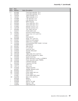
IBM 4846-545 Service Guide - Page 116
tightening
 |
View all IBM 4846-545 manuals
Add to My Manuals
Save this manual to your list of manuals |
Page 116 highlights
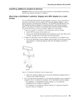
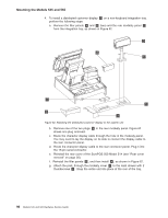
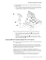
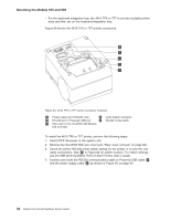
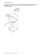
Mounting the Models 545 and 565 toward the front of the integration tray. Secure the printer by tightening the two thumbscrews on the mounting plate to the tray. c. Route the RS-232 cable A to the rear connector panel of the system unit as shown in Figure 67. Plug it into one of the three standard serial ports on the system unit. d. Route the printer power cord B toward the system and out through the hole in the integration tray, as shown in Figure 67. Note: When routing the printer and power cables, make sure that the cables are routed inside the mounting plate screws to enable correct installation of the filler panels. A B Figure 67. 4610 TF6 or TF7 cable routing 94 Models 545 and 565 Hardware Service Guide
-
 1
1 -
2
-
3
-
4
-
5
-
6
-
7
-
8
-
9
-
10
-
11
-
12
-
13
-
14
-
15
-
16
-
17
-
18
-
19
-
20
-
21
-
22
-
23
-
24
-
25
-
26
-
27
-
28
-
29
-
30
-
31
-
32
-
33
-
34
-
35
-
36
-
37
-
38
-
39
-
40
-
41
-
42
-
43
-
44
-
45
-
46
-
47
-
48
-
49
-
50
-
51
-
52
-
53
-
54
-
55
-
56
-
57
-
58
-
59
-
60
-
61
-
62
-
63
-
64
-
65
-
66
-
67
-
68
-
69
-
70
-
71
-
72
-
73
-
74
-
75
-
76
-
77
-
78
-
79
-
80
-
81
-
82
-
83
-
84
-
85
-
86
-
87
-
88
-
89
-
90
-
91
-
92
-
93
-
94
-
95
-
96
-
97
-
98
-
99
-
100
-
101
-
102
-
103
-
104
-
105
-
106
-
107
-
108
-
109
-
110
-
 111
111 -
 112
112 -
 113
113 -
 114
114 -
 115
115 -
 116
116 -
 117
117 -
 118
118 -
 119
119 -
 120
120 -
 121
121 -
122
-
123
-
124
-
125
-
126
-
127
-
128
-
129
-
130
-
131
-
132
-
133
-
134
-
135
-
136
-
137
-
138
-
139
-
140
-
141
-
142
-
143
-
144
-
145
-
146
-
147
-
148
-
149
-
150
-
151
-
152
-
153
-
154
-
155
-
156
-
157
-
158
-
159
-
160
-
161
-
162
-
163
-
164
-
165
-
166
-
167
-
168
-
169
-
170
-
171
-
172
-
173
-
174
-
175
-
176
-
177
-
178
-
179
-
180
-
181
-
182
-
183
-
184
-
185
-
186
-
187
-
188
-
189
-
190
-
191
-
192
-
193
-
194
-
195
-
196
 |
 |

toward
the
front
of
the
integration
tray.
Secure
the
printer
by
tightening
the
two
thumbscrews
on
the
mounting
plate
to
the
tray.
c.
Route
the
RS-232
cable
±A²
to
the
rear
connector
panel
of
the
system
unit
as
shown
in
Figure
67.
Plug
it
into
one
of
the
three
standard
serial
ports
on
the
system
unit.
d.
Route
the
printer
power
cord
±B²
toward
the
system
and
out
through
the
hole
in
the
integration
tray,
as
shown
in
Figure
67.
Note:
When
routing
the
printer
and
power
cables,
make
sure
that
the
cables
are
routed
inside
the
mounting
plate
screws
to
enable
correct
installation
of
the
filler
panels.
B
A
Figure
67.
4610
TF6
or
TF7
cable
routing
Mounting
the
Models
545
and
565
94
Models
545
and
565
Hardware
Service
Guide