IBM 4846-545 Service Guide - Page 91
mount, system, directly, countertop
 |
View all IBM 4846-545 manuals
Add to My Manuals
Save this manual to your list of manuals |
Page 91 highlights
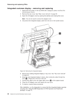
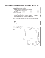
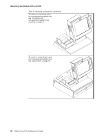
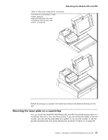
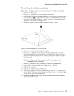
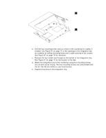
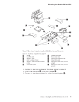
Mounting the Models 545 and 565 To mount the system directly on a countertop: Note: Before you begin, acquire two mounting screws. These are not supplied. 1. Remove the rear cover. 2. Remove the cable-tie bar by loosening the thumbscrew. 3. Use the SurePOS 500 base plate as a pattern for drilling two mounting-screw holes at location S in Figure 42. If you plan to route the cables underneath the counter, use the base plate as a pattern to drill the cable opening and for drilling the holes for the mounting screws. 4. Attach the system to the countertop with two mounting screws. S Figure 42. Attaching the base foot to the countertop 5. Connect the power cable to the power supply. 6. Connect the peripheral device cables to the appropriate ports on the rear connector panel. Make the connections on the bottom row of the connector panel first and work upward. Ensure that the cables are routed to the right of the power cord. Note: For a diagram of the port layout, see "Connectors, power, and brightness controls" on page 5. 7. Rotate the cable-tie bar back into place and tighten the thumbscrew. 8. Use tie-wraps to secure cables to the cable-tie bar, if desired. 9. Replace the rear cover. 10. Plug the AC power cord into an AC outlet. 11. After your installation is complete, switch ON the power to the SurePOS 500 and verify that the system is operating correctly by checking the indicator lights (LEDs) on the front of the touch screen. 12. Install your software. Refer to IBM SurePOS Model 545 and 565 Operating System Installation Guide. Chapter 4. Mounting the SurePOS 500 Models 545 and 565 69
-
 1
1 -
2
-
3
-
4
-
5
-
6
-
7
-
8
-
9
-
10
-
11
-
12
-
13
-
14
-
15
-
16
-
17
-
18
-
19
-
20
-
21
-
22
-
23
-
24
-
25
-
26
-
27
-
28
-
29
-
30
-
31
-
32
-
33
-
34
-
35
-
36
-
37
-
38
-
39
-
40
-
41
-
42
-
43
-
44
-
45
-
46
-
47
-
48
-
49
-
50
-
51
-
52
-
53
-
54
-
55
-
56
-
57
-
58
-
59
-
60
-
61
-
62
-
63
-
64
-
65
-
66
-
67
-
68
-
69
-
70
-
71
-
72
-
73
-
74
-
75
-
76
-
77
-
78
-
79
-
80
-
81
-
82
-
83
-
84
-
85
-
 86
86 -
 87
87 -
 88
88 -
 89
89 -
 90
90 -
 91
91 -
 92
92 -
 93
93 -
 94
94 -
 95
95 -
 96
96 -
97
-
98
-
99
-
100
-
101
-
102
-
103
-
104
-
105
-
106
-
107
-
108
-
109
-
110
-
111
-
112
-
113
-
114
-
115
-
116
-
117
-
118
-
119
-
120
-
121
-
122
-
123
-
124
-
125
-
126
-
127
-
128
-
129
-
130
-
131
-
132
-
133
-
134
-
135
-
136
-
137
-
138
-
139
-
140
-
141
-
142
-
143
-
144
-
145
-
146
-
147
-
148
-
149
-
150
-
151
-
152
-
153
-
154
-
155
-
156
-
157
-
158
-
159
-
160
-
161
-
162
-
163
-
164
-
165
-
166
-
167
-
168
-
169
-
170
-
171
-
172
-
173
-
174
-
175
-
176
-
177
-
178
-
179
-
180
-
181
-
182
-
183
-
184
-
185
-
186
-
187
-
188
-
189
-
190
-
191
-
192
-
193
-
194
-
195
-
196
 |
 |
