IBM 4846-545 Service Guide - Page 99
appropriate
 |
View all IBM 4846-545 manuals
Add to My Manuals
Save this manual to your list of manuals |
Page 99 highlights
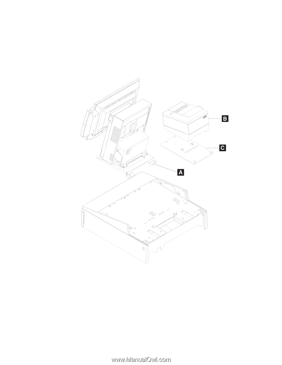
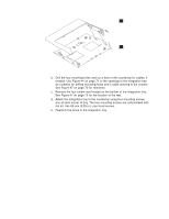
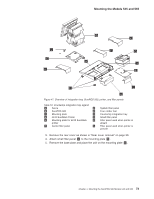
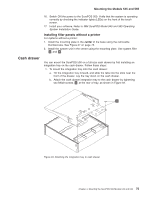
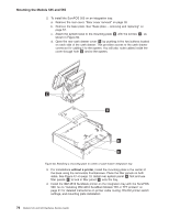
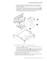
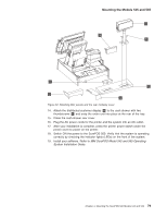
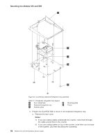
Mounting the Models 545 and 565 a. Plug the data and power cables into the printer, routing the data cable, under the cable tie bar and toward the rear connector panel as shown in Figure 65 on page 93. b. Attach the SurePOS 500 Models 545 and 565 base mounting plate A to the right side of the integration tray. Slide the front of the plate under the appropriate pair of tabs on the integration tray. Secure the rear of the plate to the tray with two thumbscrews as shown in Figure 51. Figure 51. Attaching mounting plate to the cash drawer integration tray c. Attach the printer B to the printer base mounting plate by sliding it onto the two tabs until it locks in place. d. Attach the printer base mounting plate C to the integration tray. Slide the front of the plate under the appropriate pair of tabs on the integration tray. Secure the rear of the plate to the tray with two thumbscrews. 5. Plug the cash-drawer cable into the cash drawer and route it under the cable-tie bar to the rear connector panel. 6. Plug the data and power cables into the printer, routing the data cable under the cable tie-bar and toward the rear connector panel. Chapter 4. Mounting the SurePOS 500 Models 545 and 565 77
-
 1
1 -
2
-
3
-
4
-
5
-
6
-
7
-
8
-
9
-
10
-
11
-
12
-
13
-
14
-
15
-
16
-
17
-
18
-
19
-
20
-
21
-
22
-
23
-
24
-
25
-
26
-
27
-
28
-
29
-
30
-
31
-
32
-
33
-
34
-
35
-
36
-
37
-
38
-
39
-
40
-
41
-
42
-
43
-
44
-
45
-
46
-
47
-
48
-
49
-
50
-
51
-
52
-
53
-
54
-
55
-
56
-
57
-
58
-
59
-
60
-
61
-
62
-
63
-
64
-
65
-
66
-
67
-
68
-
69
-
70
-
71
-
72
-
73
-
74
-
75
-
76
-
77
-
78
-
79
-
80
-
81
-
82
-
83
-
84
-
85
-
86
-
87
-
88
-
89
-
90
-
91
-
92
-
93
-
 94
94 -
 95
95 -
 96
96 -
 97
97 -
 98
98 -
 99
99 -
 100
100 -
 101
101 -
 102
102 -
 103
103 -
 104
104 -
105
-
106
-
107
-
108
-
109
-
110
-
111
-
112
-
113
-
114
-
115
-
116
-
117
-
118
-
119
-
120
-
121
-
122
-
123
-
124
-
125
-
126
-
127
-
128
-
129
-
130
-
131
-
132
-
133
-
134
-
135
-
136
-
137
-
138
-
139
-
140
-
141
-
142
-
143
-
144
-
145
-
146
-
147
-
148
-
149
-
150
-
151
-
152
-
153
-
154
-
155
-
156
-
157
-
158
-
159
-
160
-
161
-
162
-
163
-
164
-
165
-
166
-
167
-
168
-
169
-
170
-
171
-
172
-
173
-
174
-
175
-
176
-
177
-
178
-
179
-
180
-
181
-
182
-
183
-
184
-
185
-
186
-
187
-
188
-
189
-
190
-
191
-
192
-
193
-
194
-
195
-
196
 |
 |