IBM 4846-545 Service Guide - Page 43
Table, Symptoms, actions, continued - keyboard drivers
 |
View all IBM 4846-545 manuals
Add to My Manuals
Save this manual to your list of manuals |
Page 43 highlights
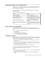
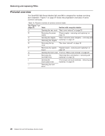
Table 11. Symptoms and actions (continued) Cash drawer does not open or close smoothly, or appears to be binding. 1. Look for items that could cause binding. Pens or paper clips trapped between the drawer and cover or the drawer and base could cause binding. 2. Compact drawer only: Remove the drawer and the rollers at the rear of the drawer and at the front of the base. Replace the rollers if necessary. 3. Determine if the slide assembly in the base is binding. Replace the slide assembly if necessary. Cash drawer not opening 1. Run the CMOS Setup Utility to make sure that IBM cash drawer setting is enabled. 2. Ensure that the cash drawer cable is securely connected. 3. Replace the cash drawer cable. 4. Replace the cash drawer latch assembly. 5. Replace the system board. Cash drawer does not open when 1. Replace the latch and the sensor assembly card. performing store transactions or running cash drawer tests, but it opens 2. Replace the cash drawer cable. when the cash drawer key is turned to 3. Replace the system board. See "System board - removing and replacing" the open position. on page 49. The status displayed by the cash drawer tests does not match the physical status of the cash drawer being tested. For example, the test indicates that cash drawer A is closed when cash drawer A is actually open. 1. Replace cable. 2. Replace the latch and the sensor assembly card. 3. Replace the system board. See "System board - removing and replacing" on page 49. Magnetic stripe reader (MSR) not reading. 1. Check the three-track MSR dip switch settings for either RS232 or keyboard interface. 2. Run the CMOS Setup Utility and check the setting in the MSR serial port. 3. Ensure that the MSR cable is securely connected. 4. Run the MSR test using the diagnostic service program. 5. Reset to factory defaults by pressing the Reset button with a paper clip. The MSR must be removed temporarily from the side of the tablet to access the reset button. Leave the MSR cable connected, and the unit powered ON when pressing the Reset button. 6. Replace the MSR. See "Magnetic stripe reader (MSR) - removing and replacing" on page 58. Operator display backlight: dark, dim, or partially lit. 1. Adjust the brightness using the button located on the front of the display. 2. Ensure tablet display cable is securely attached under display tablet and at system board. 3. Replace the LCD assembly, see "Front bezel and LCD assembly removing and replacing" on page 36. Touch screen not working. 1. Ensure tablet display cable is securely attached under display tablet and at system board. 2. Run the touch screen test using the diagnostic service program. 3. Reinstall the touch driver. 4. Replace the front touch bezel assembly. See "Front bezel and LCD assembly - removing and replacing" on page 36. 5. Replace the system board. See "System board - removing and replacing" on page 49. Chapter 2. Running diagnostics and troubleshooting 21
-
 1
1 -
2
-
3
-
4
-
5
-
6
-
7
-
8
-
9
-
10
-
11
-
12
-
13
-
14
-
15
-
16
-
17
-
18
-
19
-
20
-
21
-
22
-
23
-
24
-
25
-
26
-
27
-
28
-
29
-
30
-
31
-
32
-
33
-
34
-
35
-
36
-
37
-
 38
38 -
 39
39 -
 40
40 -
 41
41 -
 42
42 -
 43
43 -
 44
44 -
 45
45 -
 46
46 -
 47
47 -
 48
48 -
49
-
50
-
51
-
52
-
53
-
54
-
55
-
56
-
57
-
58
-
59
-
60
-
61
-
62
-
63
-
64
-
65
-
66
-
67
-
68
-
69
-
70
-
71
-
72
-
73
-
74
-
75
-
76
-
77
-
78
-
79
-
80
-
81
-
82
-
83
-
84
-
85
-
86
-
87
-
88
-
89
-
90
-
91
-
92
-
93
-
94
-
95
-
96
-
97
-
98
-
99
-
100
-
101
-
102
-
103
-
104
-
105
-
106
-
107
-
108
-
109
-
110
-
111
-
112
-
113
-
114
-
115
-
116
-
117
-
118
-
119
-
120
-
121
-
122
-
123
-
124
-
125
-
126
-
127
-
128
-
129
-
130
-
131
-
132
-
133
-
134
-
135
-
136
-
137
-
138
-
139
-
140
-
141
-
142
-
143
-
144
-
145
-
146
-
147
-
148
-
149
-
150
-
151
-
152
-
153
-
154
-
155
-
156
-
157
-
158
-
159
-
160
-
161
-
162
-
163
-
164
-
165
-
166
-
167
-
168
-
169
-
170
-
171
-
172
-
173
-
174
-
175
-
176
-
177
-
178
-
179
-
180
-
181
-
182
-
183
-
184
-
185
-
186
-
187
-
188
-
189
-
190
-
191
-
192
-
193
-
194
-
195
-
196
 |
 |