IBM 4846-545 Service Guide - Page 109
peripheral
 |
View all IBM 4846-545 manuals
Add to My Manuals
Save this manual to your list of manuals |
Page 109 highlights
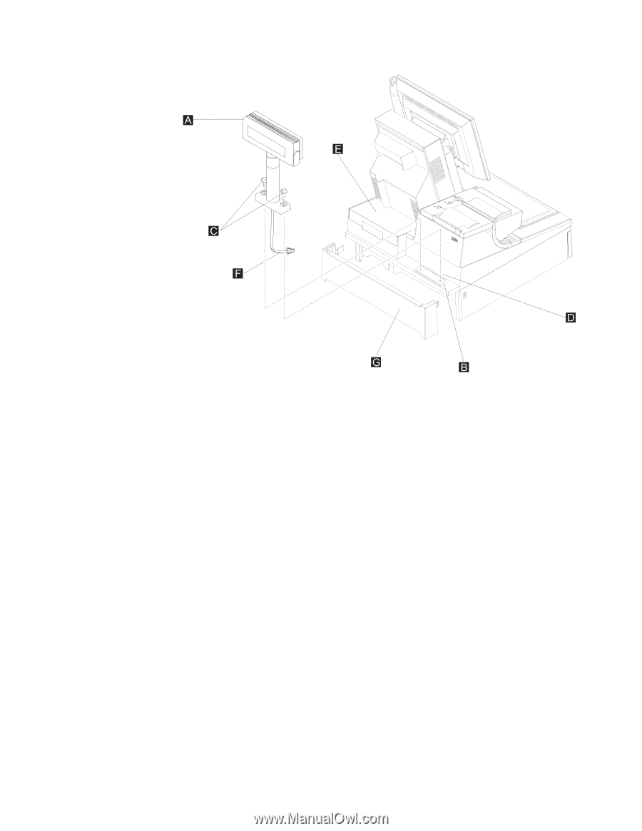
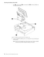
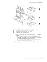
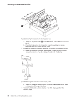
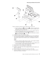
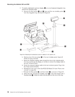
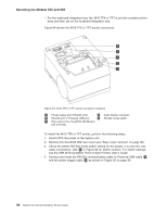
Mounting the Models 545 and 565 Figure 60. Installing the distributed customer display onto the integration tray a. Route the display cable F through hole D , as shown in Figure 60. You might need to place the display on its side to connect the display cable to the system unit rear connector panel. b. Route the display cable to the rear connector panel, passing it under the cable-tie bar, and plug it into the 15-pin serial connector. c. Attach the distributed customer display A to the cash drawer at location B with two thumbscrews C . 15. Plug the AC power cord to the power supply. 16. Connect the peripheral cables to the appropriate ports on the SurePOS 500 rear connector panel. Make the connections on the bottom row of the panel first and work upward. See "Connectors, power, and brightness controls" on page 5. Notes: a. If you are routing the cables under the counter, route all cables (including the AC power cord) through the cable-access hole. b. If you are routing the cables on top of the counter, route all cables out the rear of the system. Lay the cables flat along the countertop. 17. Use tie-wraps to secure cables to the integration tray. 18. Replace the rear cover and install the rear filler panel. 19. Attach the cash-drawer rear cover by aligning the tabs with the buttons, and push in on the cover. 20. Plug the system and printer AC power cords into an AC outlet. 21. After your installation is complete, press the printer power switch under the printer cover to power on the printer. Chapter 4. Mounting the SurePOS 500 Models 545 and 565 87
-
 1
1 -
2
-
3
-
4
-
5
-
6
-
7
-
8
-
9
-
10
-
11
-
12
-
13
-
14
-
15
-
16
-
17
-
18
-
19
-
20
-
21
-
22
-
23
-
24
-
25
-
26
-
27
-
28
-
29
-
30
-
31
-
32
-
33
-
34
-
35
-
36
-
37
-
38
-
39
-
40
-
41
-
42
-
43
-
44
-
45
-
46
-
47
-
48
-
49
-
50
-
51
-
52
-
53
-
54
-
55
-
56
-
57
-
58
-
59
-
60
-
61
-
62
-
63
-
64
-
65
-
66
-
67
-
68
-
69
-
70
-
71
-
72
-
73
-
74
-
75
-
76
-
77
-
78
-
79
-
80
-
81
-
82
-
83
-
84
-
85
-
86
-
87
-
88
-
89
-
90
-
91
-
92
-
93
-
94
-
95
-
96
-
97
-
98
-
99
-
100
-
101
-
102
-
103
-
 104
104 -
 105
105 -
 106
106 -
 107
107 -
 108
108 -
 109
109 -
 110
110 -
 111
111 -
 112
112 -
 113
113 -
 114
114 -
115
-
116
-
117
-
118
-
119
-
120
-
121
-
122
-
123
-
124
-
125
-
126
-
127
-
128
-
129
-
130
-
131
-
132
-
133
-
134
-
135
-
136
-
137
-
138
-
139
-
140
-
141
-
142
-
143
-
144
-
145
-
146
-
147
-
148
-
149
-
150
-
151
-
152
-
153
-
154
-
155
-
156
-
157
-
158
-
159
-
160
-
161
-
162
-
163
-
164
-
165
-
166
-
167
-
168
-
169
-
170
-
171
-
172
-
173
-
174
-
175
-
176
-
177
-
178
-
179
-
180
-
181
-
182
-
183
-
184
-
185
-
186
-
187
-
188
-
189
-
190
-
191
-
192
-
193
-
194
-
195
-
196
 |
 |