IBM 4846-545 Service Guide - Page 96
thumbscrews.
 |
View all IBM 4846-545 manuals
Add to My Manuals
Save this manual to your list of manuals |
Page 96 highlights
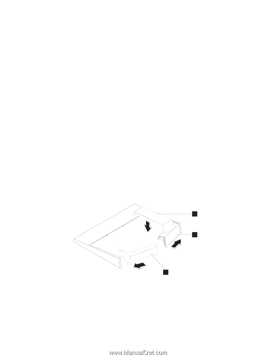
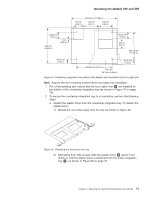
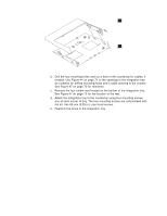
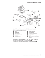
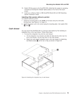
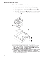
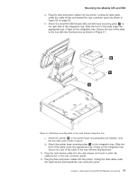
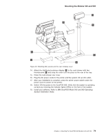
Mounting the Models 545 and 565 6. Attach the SurePOS 500 and its mounting plate C to the right side of the integration tray I as shown in Figure 47 on page 73. Slide the front of the mounting plate under the appropriate pair of tabs on the tray and secure the rear of the mounting plate to the tray with two thumbscrews. 7. Install the IBM 4610 SureMark Printer on the integration tray. Go to "Installing IBM 4610 SureMark Models TF6 or TF7 printers" on page 91 for detailed instructions on mounting plate installation and printer cable routing. a. Attach the printer to its mounting plate as shown in Figure 66 on page 93. b. Install the printer and the printer cables and route the cables as shown in Figure 65 on page 93. 8. Connect the peripheral device cables to the appropriate ports on the rear connector panel. Make the connections on the bottom row of the connector panel first and work upward. Ensure that the cables are routed to the right of the power cord. Note: For a diagram of the port layout, see "Connectors, power, and brightness controls" on page 5. 9. Use tie-wraps to secure cables to the cable-tie bar, if desired. 10. Replace the rear cover. 11. Plug the AC power cord into an AC outlet. 12. Replace the SurePOS 500 rear cover. 13. Install the filler panels after you route all the cables to your system. a. Install the outer ends of the filler panels L and G into the integration tray. Notice that the printer filler panel, shown on the right, is narrower than the system filler panel. Also, the system filler panel has a bottom slot that allows you to route the cables out the back. b. Use the narrow filler panel K to lock the filler panels together between the system and the printer. K L G Figure 48. Connecting filler panels Note: Depending on your desired configuration, you could have unused filler panels. 14. Plug the system and printer AC power cords into an AC outlet. 15. After your installation is complete, press the printer power switch under the printer cover to power On the printer. 74 Models 545 and 565 Hardware Service Guide
-
 1
1 -
2
-
3
-
4
-
5
-
6
-
7
-
8
-
9
-
10
-
11
-
12
-
13
-
14
-
15
-
16
-
17
-
18
-
19
-
20
-
21
-
22
-
23
-
24
-
25
-
26
-
27
-
28
-
29
-
30
-
31
-
32
-
33
-
34
-
35
-
36
-
37
-
38
-
39
-
40
-
41
-
42
-
43
-
44
-
45
-
46
-
47
-
48
-
49
-
50
-
51
-
52
-
53
-
54
-
55
-
56
-
57
-
58
-
59
-
60
-
61
-
62
-
63
-
64
-
65
-
66
-
67
-
68
-
69
-
70
-
71
-
72
-
73
-
74
-
75
-
76
-
77
-
78
-
79
-
80
-
81
-
82
-
83
-
84
-
85
-
86
-
87
-
88
-
89
-
90
-
 91
91 -
 92
92 -
 93
93 -
 94
94 -
 95
95 -
 96
96 -
 97
97 -
 98
98 -
 99
99 -
 100
100 -
 101
101 -
102
-
103
-
104
-
105
-
106
-
107
-
108
-
109
-
110
-
111
-
112
-
113
-
114
-
115
-
116
-
117
-
118
-
119
-
120
-
121
-
122
-
123
-
124
-
125
-
126
-
127
-
128
-
129
-
130
-
131
-
132
-
133
-
134
-
135
-
136
-
137
-
138
-
139
-
140
-
141
-
142
-
143
-
144
-
145
-
146
-
147
-
148
-
149
-
150
-
151
-
152
-
153
-
154
-
155
-
156
-
157
-
158
-
159
-
160
-
161
-
162
-
163
-
164
-
165
-
166
-
167
-
168
-
169
-
170
-
171
-
172
-
173
-
174
-
175
-
176
-
177
-
178
-
179
-
180
-
181
-
182
-
183
-
184
-
185
-
186
-
187
-
188
-
189
-
190
-
191
-
192
-
193
-
194
-
195
-
196
 |
 |