IBM 4846-545 Service Guide - Page 73
System-board, jumper, location, settings, battery, removing, replacing
 |
View all IBM 4846-545 manuals
Add to My Manuals
Save this manual to your list of manuals |
Page 73 highlights
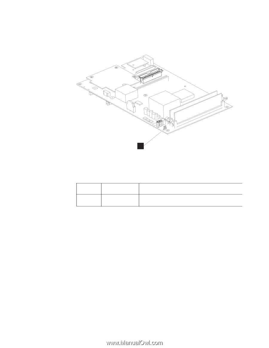
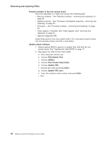
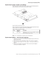
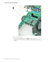
Removing and replacing FRUs System-board jumper location and settings Figure 28 shows the system-board jumper locations. See the following topics for jumper descriptions and information about jumper settings. A Figure 28. System board jumper location Table 14 describes the system board jumper setting. All jumper pins have the pin number printed on the system board for easy identification. Table 14. System board jumper settings Jumper Default pin location: Description J25 pins 1 and 2 CMOS Memory clear: To clear the CMOS, momentarily place the jumper on pins 2 and 3 Note: Pin 1 is indicated by a notched corner in the silkscreen. System-board battery - removing and replacing 1. Switch OFF the power to the SurePOS 500. Unplug the power cord from the external power source. 2. Remove the rear cover as described at "Rear cover removal" on page 30. 3. Remove the power supply. See "Power supply - removing and replacing" on page 45 4. Remove the I/O tailgate as described in "Rear connector panel (tailgate) - removing and replacing" on page 47 Chapter 3. Removing and replacing FRUs for the SurePOS 500 Models 545 and 565 51
-
 1
1 -
2
-
3
-
4
-
5
-
6
-
7
-
8
-
9
-
10
-
11
-
12
-
13
-
14
-
15
-
16
-
17
-
18
-
19
-
20
-
21
-
22
-
23
-
24
-
25
-
26
-
27
-
28
-
29
-
30
-
31
-
32
-
33
-
34
-
35
-
36
-
37
-
38
-
39
-
40
-
41
-
42
-
43
-
44
-
45
-
46
-
47
-
48
-
49
-
50
-
51
-
52
-
53
-
54
-
55
-
56
-
57
-
58
-
59
-
60
-
61
-
62
-
63
-
64
-
65
-
66
-
67
-
 68
68 -
 69
69 -
 70
70 -
 71
71 -
 72
72 -
 73
73 -
 74
74 -
 75
75 -
 76
76 -
 77
77 -
 78
78 -
79
-
80
-
81
-
82
-
83
-
84
-
85
-
86
-
87
-
88
-
89
-
90
-
91
-
92
-
93
-
94
-
95
-
96
-
97
-
98
-
99
-
100
-
101
-
102
-
103
-
104
-
105
-
106
-
107
-
108
-
109
-
110
-
111
-
112
-
113
-
114
-
115
-
116
-
117
-
118
-
119
-
120
-
121
-
122
-
123
-
124
-
125
-
126
-
127
-
128
-
129
-
130
-
131
-
132
-
133
-
134
-
135
-
136
-
137
-
138
-
139
-
140
-
141
-
142
-
143
-
144
-
145
-
146
-
147
-
148
-
149
-
150
-
151
-
152
-
153
-
154
-
155
-
156
-
157
-
158
-
159
-
160
-
161
-
162
-
163
-
164
-
165
-
166
-
167
-
168
-
169
-
170
-
171
-
172
-
173
-
174
-
175
-
176
-
177
-
178
-
179
-
180
-
181
-
182
-
183
-
184
-
185
-
186
-
187
-
188
-
189
-
190
-
191
-
192
-
193
-
194
-
195
-
196
 |
 |