IBM 4846-545 Service Guide - Page 47

Removing, replacing, SurePOS, Models

Page 47 highlights

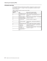
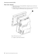
Chapter 3. Removing and replacing FRUs for the SurePOS 500 Models 545 and 565 Pictorial overview 26 Handling static-sensitive devices 28 Modular servicing and minimum tools 28 Removing the covers 29 Front (or HDD) cover removal 29 Rear cover removal 30 Opening the I/O tailgate cover 31 Top cover removal 32 Hinge cover removal 33 Display tablet - removing and replacing 34 Display tablet cable - removing and replacing 35 Front bezel and LCD assembly - removing and replacing 36 Operator card - removing and replacing 38 Tablet hinge assembly - removing and replacing 39 Hard disk drive and bracket - removing and replacing 40 Hard disk drive fan and bracket - removing and replacing 42 Hard disk drive cables - removing and replacing 43 Cable tie bar - removing and replacing 44 Power supply - removing and replacing 45 Power supply latch arm - removing and replacing 46 Rear connector panel (tailgate) - removing and replacing 47 System board - removing and replacing 49 System-board jumper location and settings 51 System-board battery - removing and replacing 51 Processor fan/heatsink assembly - removing and replacing 53 Processor module - removing and replacing 54 Memory modules - removing and replacing 55 Memory modules and industry standards 56 Base plate - removing and replacing 57 Optional features 58 Magnetic stripe reader (MSR) - removing and replacing 58 MSR hole plug - removing and replacing 58 PC card blank - removing 59 PC card - removing and replacing 59 Video adapter card- removing and replacing 61 Speaker - removing and replacing 62 Integrated customer display - removing and replacing 64 This section contains the FRU removal and replacement procedures for all SurePOS 500 Models 545 and 565 models (4846). Some procedures are for features that are not available on all models. Notes: 1. Before you perform any removal and replacement procedures, see the sections entitled "Safety Information" on page xi and "Handling static-sensitive devices" on page 28. 2. The machine serial number for the 4846 is located on the lower right, front frame. See Figure 4 on page 11. 3. Switch OFF the power to the SurePOS 500. Unplug the power cord from the external power source. © Copyright IBM Corp. 2006 25

  • 1
  • 2
  • 3
  • 4
  • 5
  • 6
  • 7
  • 8
  • 9
  • 10
  • 11
  • 12
  • 13
  • 14
  • 15
  • 16
  • 17
  • 18
  • 19
  • 20
  • 21
  • 22
  • 23
  • 24
  • 25
  • 26
  • 27
  • 28
  • 29
  • 30
  • 31
  • 32
  • 33
  • 34
  • 35
  • 36
  • 37
  • 38
  • 39
  • 40
  • 41
  • 42
  • 43
  • 44
  • 45
  • 46
  • 47
  • 48
  • 49
  • 50
  • 51
  • 52
  • 53
  • 54
  • 55
  • 56
  • 57
  • 58
  • 59
  • 60
  • 61
  • 62
  • 63
  • 64
  • 65
  • 66
  • 67
  • 68
  • 69
  • 70
  • 71
  • 72
  • 73
  • 74
  • 75
  • 76
  • 77
  • 78
  • 79
  • 80
  • 81
  • 82
  • 83
  • 84
  • 85
  • 86
  • 87
  • 88
  • 89
  • 90
  • 91
  • 92
  • 93
  • 94
  • 95
  • 96
  • 97
  • 98
  • 99
  • 100
  • 101
  • 102
  • 103
  • 104
  • 105
  • 106
  • 107
  • 108
  • 109
  • 110
  • 111
  • 112
  • 113
  • 114
  • 115
  • 116
  • 117
  • 118
  • 119
  • 120
  • 121
  • 122
  • 123
  • 124
  • 125
  • 126
  • 127
  • 128
  • 129
  • 130
  • 131
  • 132
  • 133
  • 134
  • 135
  • 136
  • 137
  • 138
  • 139
  • 140
  • 141
  • 142
  • 143
  • 144
  • 145
  • 146
  • 147
  • 148
  • 149
  • 150
  • 151
  • 152
  • 153
  • 154
  • 155
  • 156
  • 157
  • 158
  • 159
  • 160
  • 161
  • 162
  • 163
  • 164
  • 165
  • 166
  • 167
  • 168
  • 169
  • 170
  • 171
  • 172
  • 173
  • 174
  • 175
  • 176
  • 177
  • 178
  • 179
  • 180
  • 181
  • 182
  • 183
  • 184
  • 185
  • 186
  • 187
  • 188
  • 189
  • 190
  • 191
  • 192
  • 193
  • 194
  • 195
  • 196

Chapter
3.
Removing
and
replacing
FRUs
for
the
SurePOS
500
Models
545
and
565
Pictorial
overview
.
.
.
.
.
.
.
.
.
.
.
.
.
.
.
.
.
.
.
.
.
.
.
. 26
Handling
static-sensitive
devices
.
.
.
.
.
.
.
.
.
.
.
.
.
.
.
.
.
. 28
Modular
servicing
and
minimum
tools
.
.
.
.
.
.
.
.
.
.
.
.
.
.
. 28
Removing
the
covers
.
.
.
.
.
.
.
.
.
.
.
.
.
.
.
.
.
.
.
.
.
. 29
Front
(or
HDD)
cover
removal
.
.
.
.
.
.
.
.
.
.
.
.
.
.
.
.
.
. 29
Rear
cover
removal
.
.
.
.
.
.
.
.
.
.
.
.
.
.
.
.
.
.
.
.
.
. 30
Opening
the
I/O
tailgate
cover
.
.
.
.
.
.
.
.
.
.
.
.
.
.
.
.
.
. 31
Top
cover
removal
.
.
.
.
.
.
.
.
.
.
.
.
.
.
.
.
.
.
.
.
.
. 32
Hinge
cover
removal
.
.
.
.
.
.
.
.
.
.
.
.
.
.
.
.
.
.
.
.
.
. 33
Display
tablet
-
removing
and
replacing
.
.
.
.
.
.
.
.
.
.
.
.
.
.
.
. 34
Display
tablet
cable
removing
and
replacing
.
.
.
.
.
.
.
.
.
.
.
. 35
Front
bezel
and
LCD
assembly
-
removing
and
replacing
.
.
.
.
.
.
.
.
. 36
Operator
card
-
removing
and
replacing
.
.
.
.
.
.
.
.
.
.
.
.
.
.
. 38
Tablet
hinge
assembly
removing
and
replacing
.
.
.
.
.
.
.
.
.
.
.
. 39
Hard
disk
drive
and
bracket
removing
and
replacing
.
.
.
.
.
.
.
.
.
. 40
Hard
disk
drive
fan
and
bracket
removing
and
replacing
.
.
.
.
.
.
.
.
. 42
Hard
disk
drive
cables
removing
and
replacing
.
.
.
.
.
.
.
.
.
.
.
. 43
Cable
tie
bar
removing
and
replacing
.
.
.
.
.
.
.
.
.
.
.
.
.
.
.
. 44
Power
supply
removing
and
replacing
.
.
.
.
.
.
.
.
.
.
.
.
.
.
.
. 45
Power
supply
latch
arm
removing
and
replacing
.
.
.
.
.
.
.
.
.
.
.
. 46
Rear
connector
panel
(tailgate)
removing
and
replacing
.
.
.
.
.
.
.
.
. 47
System
board
removing
and
replacing
.
.
.
.
.
.
.
.
.
.
.
.
.
.
. 49
System-board
jumper
location
and
settings
.
.
.
.
.
.
.
.
.
.
.
.
. 51
System-board
battery
removing
and
replacing
.
.
.
.
.
.
.
.
.
.
.
. 51
Processor
fan/heatsink
assembly
-
removing
and
replacing
.
.
.
.
.
.
. 53
Processor
module
removing
and
replacing
.
.
.
.
.
.
.
.
.
.
.
.
. 54
Memory
modules
removing
and
replacing
.
.
.
.
.
.
.
.
.
.
.
.
.
. 55
Memory
modules
and
industry
standards
.
.
.
.
.
.
.
.
.
.
.
.
.
. 56
Base
plate
removing
and
replacing
.
.
.
.
.
.
.
.
.
.
.
.
.
.
.
.
. 57
Optional
features
.
.
.
.
.
.
.
.
.
.
.
.
.
.
.
.
.
.
.
.
.
.
.
. 58
Magnetic
stripe
reader
(MSR)
removing
and
replacing
.
.
.
.
.
.
.
.
. 58
MSR
hole
plug
removing
and
replacing
.
.
.
.
.
.
.
.
.
.
.
.
.
. 58
PC
card
blank
removing
.
.
.
.
.
.
.
.
.
.
.
.
.
.
.
.
.
.
.
. 59
PC
card
removing
and
replacing
.
.
.
.
.
.
.
.
.
.
.
.
.
.
.
.
. 59
Video
adapter
card–
removing
and
replacing
.
.
.
.
.
.
.
.
.
.
.
.
. 61
Speaker
removing
and
replacing
.
.
.
.
.
.
.
.
.
.
.
.
.
.
.
.
. 62
Integrated
customer
display
removing
and
replacing
.
.
.
.
.
.
.
.
. 64
This
section
contains
the
FRU
removal
and
replacement
procedures
for
all
SurePOS
500
Models
545
and
565
models
(4846).
Some
procedures
are
for
features
that
are
not
available
on
all
models.
Notes:
1.
Before
you
perform
any
removal
and
replacement
procedures,
see
the
sections
entitled
“Safety
Information”
on
page
xi
and
“Handling
static-sensitive
devices”
on
page
28.
2.
The
machine
serial
number
for
the
4846
is
located
on
the
lower
right,
front
frame.
See
Figure
4
on
page
11.
3.
Switch
OFF
the
power
to
the
SurePOS
500.
Unplug
the
power
cord
from
the
external
power
source.
©
Copyright
IBM
Corp.
2006
25