IBM 4846-545 Service Guide - Page 76
Processor, module, removing, replacing
 |
View all IBM 4846-545 manuals
Add to My Manuals
Save this manual to your list of manuals |
Page 76 highlights
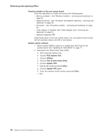
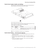
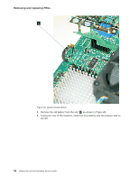
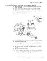
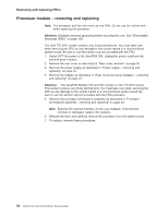
Removing and replacing FRUs Processor module - removing and replacing Note: The processor and fan sink come as one FRU. Do not use the old fan sink when replacing the processor. Attention: Establish personal grounding before touching this unit. See "Electrostatic Discharge (ESD)" on page 130. The LGA 775 CPU socket contains very finely pitched pins. You must take care when servicing the CPU as any damage to the socket results in a non-functional system board. Be sure to use the section cup tool provided with the FRU 1. Switch OFF the power to the SurePOS 500. Unplug the power cord from the external power source. 2. Remove the rear cover as described at "Rear cover removal" on page 30. 3. Remove the power supply as described in "Power supply - removing and replacing" on page 45. 4. Remove the tailgate as described in "Rear connector panel (tailgate) - removing and replacing" on page 47. Attention: The SurePOS Models 545 and 565 contain a LGA 775 CPU socket. This socket contains very finely pitched pins. You must take care when servicing the CPU as any damage to the socket results in a non-functional system board. Be sure to use the section cup tool provided with the FRU processor. 5. Remove the processor fan/heatsink assembly as described in "Processor fan/heatsink assembly - removing and replacing" on page 53. Note: Examine the thermal interface on the new heatsink. If the thermal interface is damaged, replace the heatsink. 6. Release the latch and carefully remove the processor from the system board. 7. To replace, reverse these procedures. 54 Models 545 and 565 Hardware Service Guide
-
 1
1 -
2
-
3
-
4
-
5
-
6
-
7
-
8
-
9
-
10
-
11
-
12
-
13
-
14
-
15
-
16
-
17
-
18
-
19
-
20
-
21
-
22
-
23
-
24
-
25
-
26
-
27
-
28
-
29
-
30
-
31
-
32
-
33
-
34
-
35
-
36
-
37
-
38
-
39
-
40
-
41
-
42
-
43
-
44
-
45
-
46
-
47
-
48
-
49
-
50
-
51
-
52
-
53
-
54
-
55
-
56
-
57
-
58
-
59
-
60
-
61
-
62
-
63
-
64
-
65
-
66
-
67
-
68
-
69
-
70
-
 71
71 -
 72
72 -
 73
73 -
 74
74 -
 75
75 -
 76
76 -
 77
77 -
 78
78 -
 79
79 -
 80
80 -
 81
81 -
82
-
83
-
84
-
85
-
86
-
87
-
88
-
89
-
90
-
91
-
92
-
93
-
94
-
95
-
96
-
97
-
98
-
99
-
100
-
101
-
102
-
103
-
104
-
105
-
106
-
107
-
108
-
109
-
110
-
111
-
112
-
113
-
114
-
115
-
116
-
117
-
118
-
119
-
120
-
121
-
122
-
123
-
124
-
125
-
126
-
127
-
128
-
129
-
130
-
131
-
132
-
133
-
134
-
135
-
136
-
137
-
138
-
139
-
140
-
141
-
142
-
143
-
144
-
145
-
146
-
147
-
148
-
149
-
150
-
151
-
152
-
153
-
154
-
155
-
156
-
157
-
158
-
159
-
160
-
161
-
162
-
163
-
164
-
165
-
166
-
167
-
168
-
169
-
170
-
171
-
172
-
173
-
174
-
175
-
176
-
177
-
178
-
179
-
180
-
181
-
182
-
183
-
184
-
185
-
186
-
187
-
188
-
189
-
190
-
191
-
192
-
193
-
194
-
195
-
196
 |
 |