IBM 4846-545 Service Guide - Page 100
addressable
 |
View all IBM 4846-545 manuals
Add to My Manuals
Save this manual to your list of manuals |
Page 100 highlights
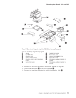
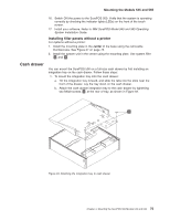
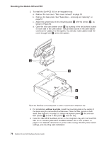
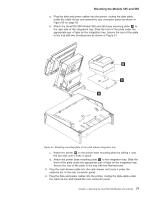
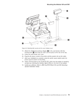
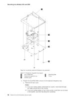
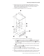
Mounting the Models 545 and 565 7. Route all cables through the hole at the center rear of the cash drawer. Then route the cables through the rear of the system, laying them flat on top of the cash-drawer integration tray. 8. If you are installing a distributed-character display or an all points addressable (APA) display, see "Mounting a distributed customer display and APA display to a cash drawer" on page 89. 9. Connect the peripheral cables to the appropriate ports on the rear connector panel. See "Connectors, power, and brightness controls" on page 5. Note: If you are installing a distributed-character display, route the cable through the unattached rear modesty panel C in Figure 52 on page 79. 10. Use tie-wraps to secure cables to the cable-tie bar. Be sure to run cables to the right of the power cable when viewed from the rear. 11. Replace the rear cover. 12. See Figure 52 on page 79. Install the filler panels after you route all the cables to your system. Note that filler panel A locks filler panels B onto the tray. Install the filler panels after you have routed all of the cables. a. Install the outer ends of the filler panels B into the integration tray. Notice that the printer filler panel, shown on the right, is narrower than the system filler panel. Also, the system filler panel has a bottom slot that allows you to route the cables out the back. b. Use the narrow filler panel A to lock the filler panels together between the system and the printer. Note: Depending upon your desired configuration, you could have unused filler panels. 13. Tilt the modesty cover C so the front hooks attach to the tray; then push down until the cover snaps into place. 78 Models 545 and 565 Hardware Service Guide
-
 1
1 -
2
-
3
-
4
-
5
-
6
-
7
-
8
-
9
-
10
-
11
-
12
-
13
-
14
-
15
-
16
-
17
-
18
-
19
-
20
-
21
-
22
-
23
-
24
-
25
-
26
-
27
-
28
-
29
-
30
-
31
-
32
-
33
-
34
-
35
-
36
-
37
-
38
-
39
-
40
-
41
-
42
-
43
-
44
-
45
-
46
-
47
-
48
-
49
-
50
-
51
-
52
-
53
-
54
-
55
-
56
-
57
-
58
-
59
-
60
-
61
-
62
-
63
-
64
-
65
-
66
-
67
-
68
-
69
-
70
-
71
-
72
-
73
-
74
-
75
-
76
-
77
-
78
-
79
-
80
-
81
-
82
-
83
-
84
-
85
-
86
-
87
-
88
-
89
-
90
-
91
-
92
-
93
-
94
-
 95
95 -
 96
96 -
 97
97 -
 98
98 -
 99
99 -
 100
100 -
 101
101 -
 102
102 -
 103
103 -
 104
104 -
 105
105 -
106
-
107
-
108
-
109
-
110
-
111
-
112
-
113
-
114
-
115
-
116
-
117
-
118
-
119
-
120
-
121
-
122
-
123
-
124
-
125
-
126
-
127
-
128
-
129
-
130
-
131
-
132
-
133
-
134
-
135
-
136
-
137
-
138
-
139
-
140
-
141
-
142
-
143
-
144
-
145
-
146
-
147
-
148
-
149
-
150
-
151
-
152
-
153
-
154
-
155
-
156
-
157
-
158
-
159
-
160
-
161
-
162
-
163
-
164
-
165
-
166
-
167
-
168
-
169
-
170
-
171
-
172
-
173
-
174
-
175
-
176
-
177
-
178
-
179
-
180
-
181
-
182
-
183
-
184
-
185
-
186
-
187
-
188
-
189
-
190
-
191
-
192
-
193
-
194
-
195
-
196
 |
 |
