IBM 4846-545 Service Guide - Page 9

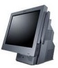
IBM 4846-545 - SurePOS 500 - 512 MB RAM Manual

Page 9 highlights

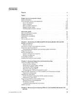
Figures 1. IBM SurePOS 500 Series configuration with optional features 1 2. Tablet connectors 5 3. Rear view of input/output available on all models 6 4. Serial number location 11 5. CMOS Setup Utility main window 14 6. CMOS reset jumper J25 15 7. Pictorial overview 27 8. Unlatching the front cover 29 9. Removing the rear cover 30 10. Opening the I/O tailgate cover 31 11. Locating the top cover release latch 32 12. Removing the hinge cover 33 13. Removing the display tablet 34 14. Removing the display tablet cable from the system board 35 15. Disconnecting the touch cable and removing the front bezel 36 16. View of L-shaped keyways 37 17. Removing the operator card 38 18. Removing the tablet hinge assembly 39 19. HDD installation 40 20. Removing the hard disk drive and bracket 41 21. Removing the HDD fan and bracket 42 22. Removing the cable tie bar 44 23. Removing the power supply 45 24. Removing the power supply latch arm 46 25. Opening the I/O tailgate cover 47 26. Removing the tailgate 48 27. Removing the system board 49 28. System board jumper location 51 29. System-board battery 52 30. Removing the processor fan/ heatsink assembly 53 31. Memory socket location 55 32. Memory module removal 56 33. Removing the base plate 57 34. Removing the MSR 58 35. Removing the PC card adapter slot blank 59 36. Removing a PC card adapter 60 37. Video adapter card removal 61 38. Removing the speaker thumbscrew 62 39. Removing the speaker and speaker EMC shield 63 40. Removing the integrated display 64 41. Base plate countertop dimensions 68 42. Attaching the base foot to the countertop 69 43. Countertop with non-keyboard-integration tray mounting 70 44. Countertop integration tray pattern with display and countertop cutout on right side 71 45. Detaching the fence from the tray 71 46. Sliding the fence off of the integration tray 72 47. Overview of integration tray, SurePOS 500, printer, and filler panels 73 48. Connecting filler panels 74 49. Attaching the integration tray to cash drawer 75 50. Attaching a mounting plate to center of cash-drawer integration tray 76 51. Attaching mounting plate to the cash drawer integration tray 77 52. Attaching filler panels and the rear modesty cover 79 53. Full-size keyboard-integration tray on a countertop 80 © Copyright IBM Corp. 2006 vii

  • 1
  • 2
  • 3
  • 4
  • 5
  • 6
  • 7
  • 8
  • 9
  • 10
  • 11
  • 12
  • 13
  • 14
  • 15
  • 16
  • 17
  • 18
  • 19
  • 20
  • 21
  • 22
  • 23
  • 24
  • 25
  • 26
  • 27
  • 28
  • 29
  • 30
  • 31
  • 32
  • 33
  • 34
  • 35
  • 36
  • 37
  • 38
  • 39
  • 40
  • 41
  • 42
  • 43
  • 44
  • 45
  • 46
  • 47
  • 48
  • 49
  • 50
  • 51
  • 52
  • 53
  • 54
  • 55
  • 56
  • 57
  • 58
  • 59
  • 60
  • 61
  • 62
  • 63
  • 64
  • 65
  • 66
  • 67
  • 68
  • 69
  • 70
  • 71
  • 72
  • 73
  • 74
  • 75
  • 76
  • 77
  • 78
  • 79
  • 80
  • 81
  • 82
  • 83
  • 84
  • 85
  • 86
  • 87
  • 88
  • 89
  • 90
  • 91
  • 92
  • 93
  • 94
  • 95
  • 96
  • 97
  • 98
  • 99
  • 100
  • 101
  • 102
  • 103
  • 104
  • 105
  • 106
  • 107
  • 108
  • 109
  • 110
  • 111
  • 112
  • 113
  • 114
  • 115
  • 116
  • 117
  • 118
  • 119
  • 120
  • 121
  • 122
  • 123
  • 124
  • 125
  • 126
  • 127
  • 128
  • 129
  • 130
  • 131
  • 132
  • 133
  • 134
  • 135
  • 136
  • 137
  • 138
  • 139
  • 140
  • 141
  • 142
  • 143
  • 144
  • 145
  • 146
  • 147
  • 148
  • 149
  • 150
  • 151
  • 152
  • 153
  • 154
  • 155
  • 156
  • 157
  • 158
  • 159
  • 160
  • 161
  • 162
  • 163
  • 164
  • 165
  • 166
  • 167
  • 168
  • 169
  • 170
  • 171
  • 172
  • 173
  • 174
  • 175
  • 176
  • 177
  • 178
  • 179
  • 180
  • 181
  • 182
  • 183
  • 184
  • 185
  • 186
  • 187
  • 188
  • 189
  • 190
  • 191
  • 192
  • 193
  • 194
  • 195
  • 196

Figures
1.
IBM
SurePOS
500
Series
configuration
with
optional
features
.
.
.
.
.
.
.
.
.
.
.
.
.
.
.1
2.
Tablet
connectors
.
.
.
.
.
.
.
.
.
.
.
.
.
.
.
.
.
.
.
.
.
.
.
.
.
.
.
.
.
.
.5
3.
Rear
view
of
input/output
available
on
all
models
.
.
.
.
.
.
.
.
.
.
.
.
.
.
.
.
.
.
.6
4.
Serial
number
location
.
.
.
.
.
.
.
.
.
.
.
.
.
.
.
.
.
.
.
.
.
.
.
.
.
.
.
.
. 11
5.
CMOS
Setup
Utility
main
window
.
.
.
.
.
.
.
.
.
.
.
.
.
.
.
.
.
.
.
.
.
.
.
.
. 14
6.
CMOS
reset
jumper
J25
.
.
.
.
.
.
.
.
.
.
.
.
.
.
.
.
.
.
.
.
.
.
.
.
.
.
.
. 15
7.
Pictorial
overview
.
.
.
.
.
.
.
.
.
.
.
.
.
.
.
.
.
.
.
.
.
.
.
.
.
.
.
.
.
.
. 27
8.
Unlatching
the
front
cover
.
.
.
.
.
.
.
.
.
.
.
.
.
.
.
.
.
.
.
.
.
.
.
.
.
.
. 29
9.
Removing
the
rear
cover
.
.
.
.
.
.
.
.
.
.
.
.
.
.
.
.
.
.
.
.
.
.
.
.
.
.
.
. 30
10.
Opening
the
I/O
tailgate
cover
.
.
.
.
.
.
.
.
.
.
.
.
.
.
.
.
.
.
.
.
.
.
.
.
.
. 31
11.
Locating
the
top
cover
release
latch
.
.
.
.
.
.
.
.
.
.
.
.
.
.
.
.
.
.
.
.
.
.
.
. 32
12.
Removing
the
hinge
cover
.
.
.
.
.
.
.
.
.
.
.
.
.
.
.
.
.
.
.
.
.
.
.
.
.
.
. 33
13.
Removing
the
display
tablet
.
.
.
.
.
.
.
.
.
.
.
.
.
.
.
.
.
.
.
.
.
.
.
.
.
.
. 34
14.
Removing
the
display
tablet
cable
from
the
system
board
.
.
.
.
.
.
.
.
.
.
.
.
.
.
.
. 35
15.
Disconnecting
the
touch
cable
and
removing
the
front
bezel
.
.
.
.
.
.
.
.
.
.
.
.
.
.
. 36
16.
View
of
L-shaped
keyways
.
.
.
.
.
.
.
.
.
.
.
.
.
.
.
.
.
.
.
.
.
.
.
.
.
.
. 37
17.
Removing
the
operator
card
.
.
.
.
.
.
.
.
.
.
.
.
.
.
.
.
.
.
.
.
.
.
.
.
.
.
. 38
18.
Removing
the
tablet
hinge
assembly
.
.
.
.
.
.
.
.
.
.
.
.
.
.
.
.
.
.
.
.
.
.
. 39
19.
HDD
installation
.
.
.
.
.
.
.
.
.
.
.
.
.
.
.
.
.
.
.
.
.
.
.
.
.
.
.
.
.
.
. 40
20.
Removing
the
hard
disk
drive
and
bracket
.
.
.
.
.
.
.
.
.
.
.
.
.
.
.
.
.
.
.
.
. 41
21.
Removing
the
HDD
fan
and
bracket
.
.
.
.
.
.
.
.
.
.
.
.
.
.
.
.
.
.
.
.
.
.
.
. 42
22.
Removing
the
cable
tie
bar
.
.
.
.
.
.
.
.
.
.
.
.
.
.
.
.
.
.
.
.
.
.
.
.
.
.
. 44
23.
Removing
the
power
supply
.
.
.
.
.
.
.
.
.
.
.
.
.
.
.
.
.
.
.
.
.
.
.
.
.
.
. 45
24.
Removing
the
power
supply
latch
arm
.
.
.
.
.
.
.
.
.
.
.
.
.
.
.
.
.
.
.
.
.
.
. 46
25.
Opening
the
I/O
tailgate
cover
.
.
.
.
.
.
.
.
.
.
.
.
.
.
.
.
.
.
.
.
.
.
.
.
.
. 47
26.
Removing
the
tailgate
.
.
.
.
.
.
.
.
.
.
.
.
.
.
.
.
.
.
.
.
.
.
.
.
.
.
.
.
. 48
27.
Removing
the
system
board
.
.
.
.
.
.
.
.
.
.
.
.
.
.
.
.
.
.
.
.
.
.
.
.
.
.
. 49
28.
System
board
jumper
location
.
.
.
.
.
.
.
.
.
.
.
.
.
.
.
.
.
.
.
.
.
.
.
.
.
. 51
29.
System-board
battery
.
.
.
.
.
.
.
.
.
.
.
.
.
.
.
.
.
.
.
.
.
.
.
.
.
.
.
.
. 52
30.
Removing
the
processor
fan/
heatsink
assembly
.
.
.
.
.
.
.
.
.
.
.
.
.
.
.
.
.
.
. 53
31.
Memory
socket
location
.
.
.
.
.
.
.
.
.
.
.
.
.
.
.
.
.
.
.
.
.
.
.
.
.
.
.
. 55
32.
Memory
module
removal
.
.
.
.
.
.
.
.
.
.
.
.
.
.
.
.
.
.
.
.
.
.
.
.
.
.
.
. 56
33.
Removing
the
base
plate
.
.
.
.
.
.
.
.
.
.
.
.
.
.
.
.
.
.
.
.
.
.
.
.
.
.
.
. 57
34.
Removing
the
MSR
.
.
.
.
.
.
.
.
.
.
.
.
.
.
.
.
.
.
.
.
.
.
.
.
.
.
.
.
.
. 58
35.
Removing
the
PC
card
adapter
slot
blank
.
.
.
.
.
.
.
.
.
.
.
.
.
.
.
.
.
.
.
.
.
. 59
36.
Removing
a
PC
card
adapter
.
.
.
.
.
.
.
.
.
.
.
.
.
.
.
.
.
.
.
.
.
.
.
.
.
. 60
37.
Video
adapter
card
removal
.
.
.
.
.
.
.
.
.
.
.
.
.
.
.
.
.
.
.
.
.
.
.
.
.
.
. 61
38.
Removing
the
speaker
thumbscrew
.
.
.
.
.
.
.
.
.
.
.
.
.
.
.
.
.
.
.
.
.
.
.
. 62
39.
Removing
the
speaker
and
speaker
EMC
shield
.
.
.
.
.
.
.
.
.
.
.
.
.
.
.
.
.
.
. 63
40.
Removing
the
integrated
display
.
.
.
.
.
.
.
.
.
.
.
.
.
.
.
.
.
.
.
.
.
.
.
.
. 64
41.
Base
plate
countertop
dimensions
.
.
.
.
.
.
.
.
.
.
.
.
.
.
.
.
.
.
.
.
.
.
.
. 68
42.
Attaching
the
base
foot
to
the
countertop
.
.
.
.
.
.
.
.
.
.
.
.
.
.
.
.
.
.
.
.
.
. 69
43.
Countertop
with
non-keyboard-integration
tray
mounting
.
.
.
.
.
.
.
.
.
.
.
.
.
.
.
. 70
44.
Countertop
integration
tray
pattern
with
display
and
countertop
cutout
on
right
side
.
.
.
.
.
. 71
45.
Detaching
the
fence
from
the
tray
.
.
.
.
.
.
.
.
.
.
.
.
.
.
.
.
.
.
.
.
.
.
.
.
. 71
46.
Sliding
the
fence
off
of
the
integration
tray
.
.
.
.
.
.
.
.
.
.
.
.
.
.
.
.
.
.
.
.
. 72
47.
Overview
of
integration
tray,
SurePOS
500,
printer,
and
filler
panels
.
.
.
.
.
.
.
.
.
.
.
. 73
48.
Connecting
filler
panels
.
.
.
.
.
.
.
.
.
.
.
.
.
.
.
.
.
.
.
.
.
.
.
.
.
.
.
. 74
49.
Attaching
the
integration
tray
to
cash
drawer
.
.
.
.
.
.
.
.
.
.
.
.
.
.
.
.
.
.
.
. 75
50.
Attaching
a
mounting
plate
to
center
of
cash-drawer
integration
tray
.
.
.
.
.
.
.
.
.
.
.
. 76
51.
Attaching
mounting
plate
to
the
cash
drawer
integration
tray
.
.
.
.
.
.
.
.
.
.
.
.
.
.
. 77
52.
Attaching
filler
panels
and
the
rear
modesty
cover
.
.
.
.
.
.
.
.
.
.
.
.
.
.
.
.
.
. 79
53.
Full-size
keyboard-integration
tray
on
a
countertop
.
.
.
.
.
.
.
.
.
.
.
.
.
.
.
.
.
. 80
©
Copyright
IBM
Corp.
2006
vii