IBM 4846-545 Service Guide - Page 94
integration
 |
View all IBM 4846-545 manuals
Add to My Manuals
Save this manual to your list of manuals |
Page 94 highlights
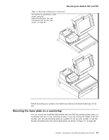
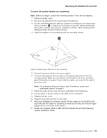
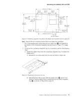
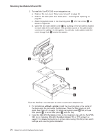
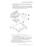
Mounting the Models 545 and 565 B A Figure 46. Sliding the fence off of the integration tray b. Drill the four mounting holes and cut a hole in the countertop for cables, if needed. Use Figure 44 on page 71 or the openings in the integration tray as a pattern for drilling mounting holes and a cable opening in the counter. See Figure 47 on page 73 for reference. c. Remove the four rubber feet located on the bottom of the integration tray. See Figure 47 on page 73 for the location of the feet. d. Attach the integration tray to the countertop using four mounting screws, one at each corner of tray. The four mounting screws are not provided with the kit. Use 60-mm (0.25-in.), pan-head screws. e. Reattach the fence to the integration tray. 72 Models 545 and 565 Hardware Service Guide
-
 1
1 -
2
-
3
-
4
-
5
-
6
-
7
-
8
-
9
-
10
-
11
-
12
-
13
-
14
-
15
-
16
-
17
-
18
-
19
-
20
-
21
-
22
-
23
-
24
-
25
-
26
-
27
-
28
-
29
-
30
-
31
-
32
-
33
-
34
-
35
-
36
-
37
-
38
-
39
-
40
-
41
-
42
-
43
-
44
-
45
-
46
-
47
-
48
-
49
-
50
-
51
-
52
-
53
-
54
-
55
-
56
-
57
-
58
-
59
-
60
-
61
-
62
-
63
-
64
-
65
-
66
-
67
-
68
-
69
-
70
-
71
-
72
-
73
-
74
-
75
-
76
-
77
-
78
-
79
-
80
-
81
-
82
-
83
-
84
-
85
-
86
-
87
-
88
-
 89
89 -
 90
90 -
 91
91 -
 92
92 -
 93
93 -
 94
94 -
 95
95 -
 96
96 -
 97
97 -
 98
98 -
 99
99 -
100
-
101
-
102
-
103
-
104
-
105
-
106
-
107
-
108
-
109
-
110
-
111
-
112
-
113
-
114
-
115
-
116
-
117
-
118
-
119
-
120
-
121
-
122
-
123
-
124
-
125
-
126
-
127
-
128
-
129
-
130
-
131
-
132
-
133
-
134
-
135
-
136
-
137
-
138
-
139
-
140
-
141
-
142
-
143
-
144
-
145
-
146
-
147
-
148
-
149
-
150
-
151
-
152
-
153
-
154
-
155
-
156
-
157
-
158
-
159
-
160
-
161
-
162
-
163
-
164
-
165
-
166
-
167
-
168
-
169
-
170
-
171
-
172
-
173
-
174
-
175
-
176
-
177
-
178
-
179
-
180
-
181
-
182
-
183
-
184
-
185
-
186
-
187
-
188
-
189
-
190
-
191
-
192
-
193
-
194
-
195
-
196
 |
 |
