IBM 4846-545 Service Guide - Page 114
connections.
 |
View all IBM 4846-545 manuals
Add to My Manuals
Save this manual to your list of manuals |
Page 114 highlights
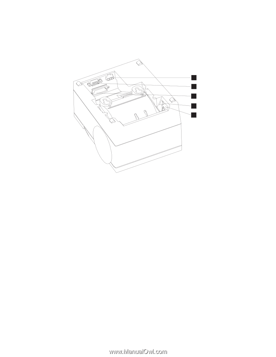
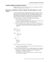
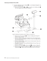
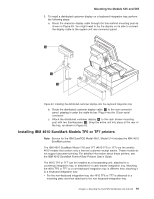
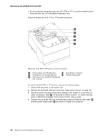
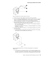
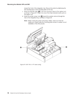
Mounting the Models 545 and 565 v For the keyboard integration tray, the 4610 TF6 or TF7 is set into a plastic printer base and then set on the keyboard integration tray. Figure 64 shows the 4610 TF6 or TF7 printer connectors. A B C E D Figure 64. 4610 TF6 or TF7 printer connector locations A Power supply port (RS-232 only) D Cash drawer connector B RS-232 port or Powered USB port E RS-232 mode switch C (Not used on the SurePOS 500 Models 545 and 565) To install the 4610 TF6 or TF7 printer, perform the following steps: 1. Switch OFF the power at the system unit. 2. Remove the SurePOS 500 rear cover (see "Rear cover removal" on page 30). 3. Check the printer RS-232 mode-switch setting for the printer. It is near the rear cable connections. See E in Figure 64 for switch location. For switch settings, see the IBM 4610 SureMark Point-of-Sale Printers User's Guide. 4. Connect and route the RS-232 communication cable or Powered USB cable A and the power supply cable B as shown in Figure 65 on page 93. 92 Models 545 and 565 Hardware Service Guide
-
 1
1 -
2
-
3
-
4
-
5
-
6
-
7
-
8
-
9
-
10
-
11
-
12
-
13
-
14
-
15
-
16
-
17
-
18
-
19
-
20
-
21
-
22
-
23
-
24
-
25
-
26
-
27
-
28
-
29
-
30
-
31
-
32
-
33
-
34
-
35
-
36
-
37
-
38
-
39
-
40
-
41
-
42
-
43
-
44
-
45
-
46
-
47
-
48
-
49
-
50
-
51
-
52
-
53
-
54
-
55
-
56
-
57
-
58
-
59
-
60
-
61
-
62
-
63
-
64
-
65
-
66
-
67
-
68
-
69
-
70
-
71
-
72
-
73
-
74
-
75
-
76
-
77
-
78
-
79
-
80
-
81
-
82
-
83
-
84
-
85
-
86
-
87
-
88
-
89
-
90
-
91
-
92
-
93
-
94
-
95
-
96
-
97
-
98
-
99
-
100
-
101
-
102
-
103
-
104
-
105
-
106
-
107
-
108
-
 109
109 -
 110
110 -
 111
111 -
 112
112 -
 113
113 -
 114
114 -
 115
115 -
 116
116 -
 117
117 -
 118
118 -
 119
119 -
120
-
121
-
122
-
123
-
124
-
125
-
126
-
127
-
128
-
129
-
130
-
131
-
132
-
133
-
134
-
135
-
136
-
137
-
138
-
139
-
140
-
141
-
142
-
143
-
144
-
145
-
146
-
147
-
148
-
149
-
150
-
151
-
152
-
153
-
154
-
155
-
156
-
157
-
158
-
159
-
160
-
161
-
162
-
163
-
164
-
165
-
166
-
167
-
168
-
169
-
170
-
171
-
172
-
173
-
174
-
175
-
176
-
177
-
178
-
179
-
180
-
181
-
182
-
183
-
184
-
185
-
186
-
187
-
188
-
189
-
190
-
191
-
192
-
193
-
194
-
195
-
196
 |
 |