IBM 4846-545 Service Guide - Page 112
non-keyboard
 |
View all IBM 4846-545 manuals
Add to My Manuals
Save this manual to your list of manuals |
Page 112 highlights
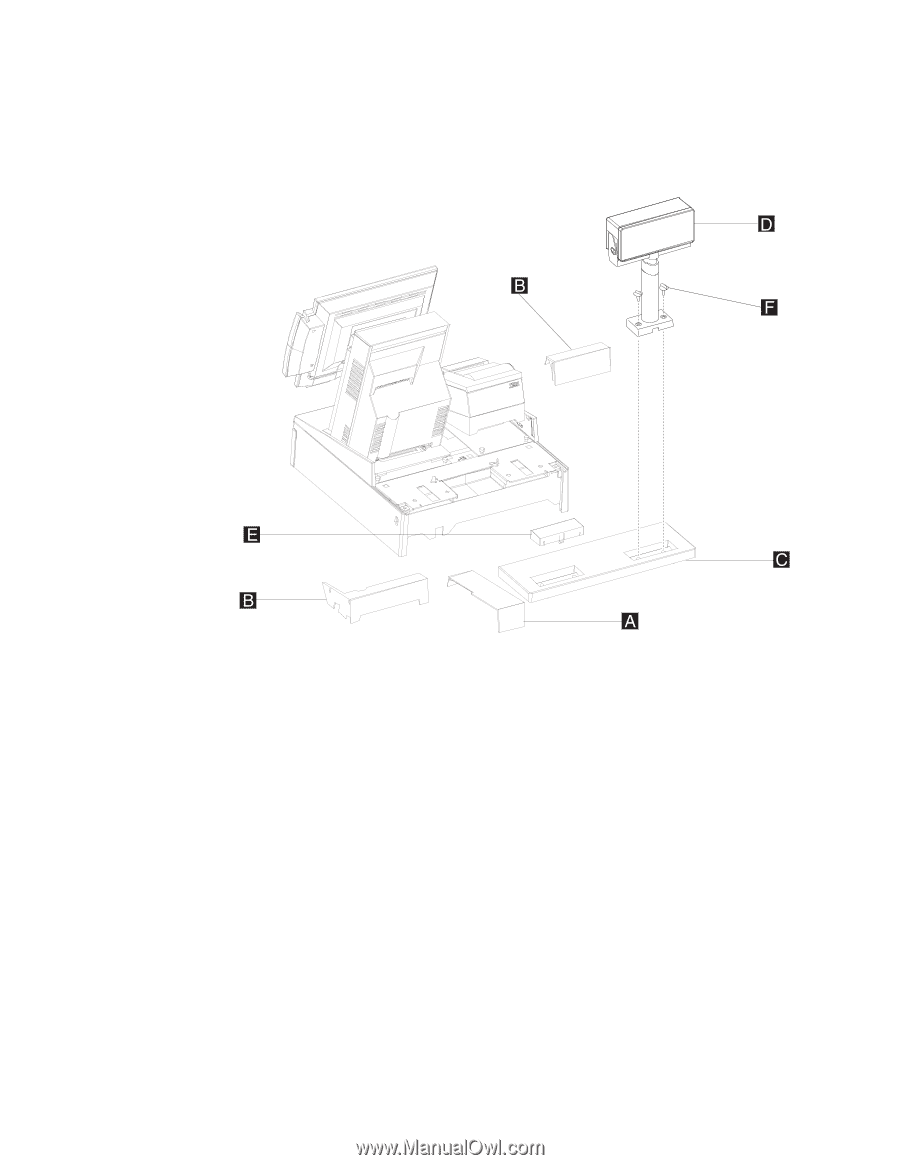
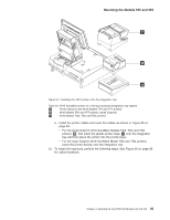
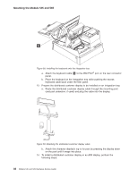
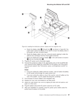
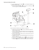
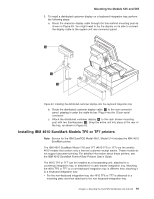
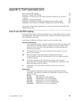
Mounting the Models 545 and 565 4. To install a distributed customer display D on a non-keyboard integration tray, perform the following steps: a. Remove the filler panels A and B (two) and the rear modesty panel C from the integration tray, as shown in Figure 62. Figure 62. Attaching the distributed customer display to the system unit b. Remove one of the two plugs E in the rear modesty panel. Figure 62 shows one plug removed. c. Route the character display cable through the hole in the modesty panel. You may need to lay the display on its side to connect the display cable to the rear connector panel. d. Route the character display cable to the rear connector panel. Plug it into the 15-pin serial connector. e. Reinstall the rear cover of the SurePOS 500 Model 514 (see "Rear cover removal" on page 30). f. Reinstall the filler panels B , and then install A , as shown in Figure 62. g. Attach the post, through the modesty cover C to the cash drawer with 2 thumbscrews F . Snap the entire unit into place at the rear of the tray. 90 Models 545 and 565 Hardware Service Guide
-
 1
1 -
2
-
3
-
4
-
5
-
6
-
7
-
8
-
9
-
10
-
11
-
12
-
13
-
14
-
15
-
16
-
17
-
18
-
19
-
20
-
21
-
22
-
23
-
24
-
25
-
26
-
27
-
28
-
29
-
30
-
31
-
32
-
33
-
34
-
35
-
36
-
37
-
38
-
39
-
40
-
41
-
42
-
43
-
44
-
45
-
46
-
47
-
48
-
49
-
50
-
51
-
52
-
53
-
54
-
55
-
56
-
57
-
58
-
59
-
60
-
61
-
62
-
63
-
64
-
65
-
66
-
67
-
68
-
69
-
70
-
71
-
72
-
73
-
74
-
75
-
76
-
77
-
78
-
79
-
80
-
81
-
82
-
83
-
84
-
85
-
86
-
87
-
88
-
89
-
90
-
91
-
92
-
93
-
94
-
95
-
96
-
97
-
98
-
99
-
100
-
101
-
102
-
103
-
104
-
105
-
106
-
 107
107 -
 108
108 -
 109
109 -
 110
110 -
 111
111 -
 112
112 -
 113
113 -
 114
114 -
 115
115 -
 116
116 -
 117
117 -
118
-
119
-
120
-
121
-
122
-
123
-
124
-
125
-
126
-
127
-
128
-
129
-
130
-
131
-
132
-
133
-
134
-
135
-
136
-
137
-
138
-
139
-
140
-
141
-
142
-
143
-
144
-
145
-
146
-
147
-
148
-
149
-
150
-
151
-
152
-
153
-
154
-
155
-
156
-
157
-
158
-
159
-
160
-
161
-
162
-
163
-
164
-
165
-
166
-
167
-
168
-
169
-
170
-
171
-
172
-
173
-
174
-
175
-
176
-
177
-
178
-
179
-
180
-
181
-
182
-
183
-
184
-
185
-
186
-
187
-
188
-
189
-
190
-
191
-
192
-
193
-
194
-
195
-
196
 |
 |