Canon XF705 Instruction Manual - Page 147
Connecting to an External Monitor, Using the SDI Terminal, elect, DI/HDMI Max Re, elect the de
 |
View all Canon XF705 manuals
Add to My Manuals
Save this manual to your list of manuals |
Page 147 highlights
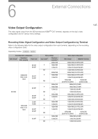
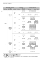
Connecting to an External Monitor Connecting to an External Monitor When you connect the camcorder to an external monitor (to monitor the recording or for playback), use the terminal on the camcorder that matches the one you wish to use on the monitor. Then, select the video signal output configuration (A 145). Operating modes: 147 Connection diagram We recommend that you power the camcorder from a power outlet using the compact power adapter. SDI terminal BNC cable (commercially available) SDI inputs External monitor HDMI cable (commercially available) HDMI OUT terminal HDMI inputs Using the SDI Terminal The digital signal that is output from the SDI terminal includes the video signal, audio signal (up to 4 channels), time code signal and the recording command signal. When using the SDI terminal, you can output various assistance displays (onscreen displays, markers, etc.) in order to check them also on an external monitor. 1 Select [SDI/HDMI Max Res.]. > [B " System Setup] > [SDI/HDMI Max Res.] 2 Select the desired option and then press SET. 3 Select [SDI Output]. > [B " System Setup] > [SDI Output] 4 Select [On] and then press SET. 5 Select [3G-SDI Mapping]. > [B " System Setup] > [3G-SDI Mapping] 6 Select the desired option and then press SET. • You can select a video output signal compliant with Level A or Level B of the SMPTE ST 425-1 standard.
-
 1
1 -
2
-
3
-
4
-
5
-
6
-
7
-
8
-
9
-
10
-
11
-
12
-
13
-
14
-
15
-
16
-
17
-
18
-
19
-
20
-
21
-
22
-
23
-
24
-
25
-
26
-
27
-
28
-
29
-
30
-
31
-
32
-
33
-
34
-
35
-
36
-
37
-
38
-
39
-
40
-
41
-
42
-
43
-
44
-
45
-
46
-
47
-
48
-
49
-
50
-
51
-
52
-
53
-
54
-
55
-
56
-
57
-
58
-
59
-
60
-
61
-
62
-
63
-
64
-
65
-
66
-
67
-
68
-
69
-
70
-
71
-
72
-
73
-
74
-
75
-
76
-
77
-
78
-
79
-
80
-
81
-
82
-
83
-
84
-
85
-
86
-
87
-
88
-
89
-
90
-
91
-
92
-
93
-
94
-
95
-
96
-
97
-
98
-
99
-
100
-
101
-
102
-
103
-
104
-
105
-
106
-
107
-
108
-
109
-
110
-
111
-
112
-
113
-
114
-
115
-
116
-
117
-
118
-
119
-
120
-
121
-
122
-
123
-
124
-
125
-
126
-
127
-
128
-
129
-
130
-
131
-
132
-
133
-
134
-
135
-
136
-
137
-
138
-
139
-
140
-
141
-
 142
142 -
 143
143 -
 144
144 -
 145
145 -
 146
146 -
 147
147 -
 148
148 -
 149
149 -
 150
150 -
 151
151 -
 152
152 -
153
-
154
-
155
-
156
-
157
-
158
-
159
-
160
-
161
-
162
-
163
-
164
-
165
-
166
-
167
-
168
-
169
-
170
-
171
-
172
-
173
-
174
-
175
-
176
-
177
-
178
-
179
-
180
-
181
-
182
-
183
-
184
-
185
-
186
-
187
-
188
-
189
-
190
-
191
-
192
-
193
-
194
-
195
-
196
-
197
-
198
-
199
-
200
-
201
-
202
-
203
-
204
-
205
-
206
-
207
-
208
-
209
-
210
-
211
-
212
-
213
-
214
-
215
-
216
-
217
-
218
-
219
-
220
-
221
-
222
-
223
-
224
-
225
-
226
-
227
-
228
-
229
-
230
-
231
-
232
-
233
-
234
 |
 |
