Dell PowerEdge R905 Hardware Owner's Manual (PDF) - Page 101
Installing a Processor, Leave the release lever up so that the socket is ready for the new processor.
 |
View all Dell PowerEdge R905 manuals
Add to My Manuals
Save this manual to your list of manuals |
Page 101 highlights
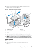
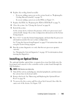
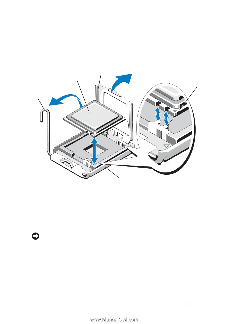
12 Pull the socket-release lever 90 degrees upward until the processor is released from the socket. See Figure 3-21. Figure 3-21. Removing and Installing the Processor 3 2 4 1 5 1 socket-release lever 3 processor shield 5 socket 2 processor 4 socket keys (2) 13 Open the processor shield and then lift the processor out of the socket. Leave the release lever up so that the socket is ready for the new processor. NOTICE: Be careful not to bend any of the pins on the socket when removing the processor. Bending the pins can permanently damage the socket and system board. Installing a Processor 1 Unpack the new processor. 2 Align the processor with the two socket keys on the socket. See Figure 3-21. Installing System Components 101
-
 1
1 -
2
-
3
-
4
-
5
-
6
-
7
-
8
-
9
-
10
-
11
-
12
-
13
-
14
-
15
-
16
-
17
-
18
-
19
-
20
-
21
-
22
-
23
-
24
-
25
-
26
-
27
-
28
-
29
-
30
-
31
-
32
-
33
-
34
-
35
-
36
-
37
-
38
-
39
-
40
-
41
-
42
-
43
-
44
-
45
-
46
-
47
-
48
-
49
-
50
-
51
-
52
-
53
-
54
-
55
-
56
-
57
-
58
-
59
-
60
-
61
-
62
-
63
-
64
-
65
-
66
-
67
-
68
-
69
-
70
-
71
-
72
-
73
-
74
-
75
-
76
-
77
-
78
-
79
-
80
-
81
-
82
-
83
-
84
-
85
-
86
-
87
-
88
-
89
-
90
-
91
-
92
-
93
-
94
-
95
-
 96
96 -
 97
97 -
 98
98 -
 99
99 -
 100
100 -
 101
101 -
 102
102 -
 103
103 -
 104
104 -
 105
105 -
 106
106 -
107
-
108
-
109
-
110
-
111
-
112
-
113
-
114
-
115
-
116
-
117
-
118
-
119
-
120
-
121
-
122
-
123
-
124
-
125
-
126
-
127
-
128
-
129
-
130
-
131
-
132
-
133
-
134
-
135
-
136
-
137
-
138
-
139
-
140
-
141
-
142
-
143
-
144
-
145
-
146
-
147
-
148
-
149
-
150
-
151
-
152
-
153
-
154
-
155
-
156
-
157
-
158
-
159
-
160
-
161
-
162
-
163
-
164
-
165
-
166
-
167
-
168
-
169
-
170
-
171
-
172
-
173
-
174
-
175
-
176
-
177
-
178
-
179
-
180
-
181
-
182
-
183
-
184
-
185
-
186
-
187
-
188
-
189
-
190
-
191
-
192
-
193
-
194
-
195
-
196
-
197
-
198
 |
 |
Installing System Components
101
12
Pull the socket-release lever 90 degrees upward until the processor is
released from the socket. See Figure 3-21.
Figure 3-21.
Removing and Installing the Processor
13
Open the processor shield and then lift the processor out of the socket.
Leave the release lever up so that the socket is ready for the new processor.
NOTICE:
Be careful not to bend any of the pins on the socket when removing the
processor. Bending the pins can permanently damage the socket and system board.
Installing a Processor
1
Unpack the new processor.
2
Align the
p
rocessor with the two
socket keys on t
he socket
. See
Figure 3-21.
1
socket-release lever
2
processor
3
processor shield
4
socket keys (2)
5
socket
2
4
5
1
3