Dell PowerEdge R905 Hardware Owner's Manual (PDF) - Page 83
RAC Card, Installing an Optional RAC Card
 |
View all Dell PowerEdge R905 manuals
Add to My Manuals
Save this manual to your list of manuals |
Page 83 highlights
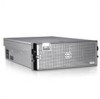
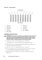
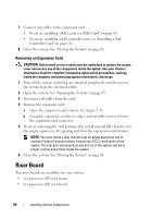
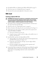
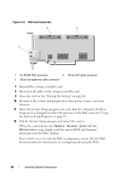
3 Reinstall the PEM. See "Replacing the PEM or PEM Shell" on page 76. 4 Close the system. See "Closing the System" on page 66. 5 Reconnect the system and peripherals to their power sources. RAC Card Installing an Optional RAC Card CAUTION: Only trained service technicians are authorized to remove the system cover and access any of the components inside the system. See your Product Information Guide for complete information about safety precautions, working inside the computer, and protecting against electrostatic discharge. 1 Turn off the system, including any attached peripherals, and disconnect the system from the electrical outlet. 2 Open the system. See "Opening the System" on page 65. 3 Remove the plastic filler plug from the system back panel. See Figure 1-3. 4 Temporarily remove the storage controller card from the expansion slot labeled INTERNAL STORAGE: a Disconnect all cables from the card. b Grasp the storage controller card by its edges, and carefully remove it from the card connector. 5 Install the RAC card in the slot labeled RAC_CONN: a Angle the RAC card so that the NIC connector fits through the backpanel RAC NIC opening. See Figure 3-14. b Position the card so that the card-edge connector aligns with the expansion-card connector. c Insert the card-edge connector firmly into the expansion-card connector until the card is fully seated. 6 Connect the 50-pin management cable and the 44-pin MII cable supplied with the RAC to the two connectors on the RAC card (see Figure 3-14), and to the two corresponding connectors on the system board (see Figure 6-1). Installing System Components 83
-
 1
1 -
2
-
3
-
4
-
5
-
6
-
7
-
8
-
9
-
10
-
11
-
12
-
13
-
14
-
15
-
16
-
17
-
18
-
19
-
20
-
21
-
22
-
23
-
24
-
25
-
26
-
27
-
28
-
29
-
30
-
31
-
32
-
33
-
34
-
35
-
36
-
37
-
38
-
39
-
40
-
41
-
42
-
43
-
44
-
45
-
46
-
47
-
48
-
49
-
50
-
51
-
52
-
53
-
54
-
55
-
56
-
57
-
58
-
59
-
60
-
61
-
62
-
63
-
64
-
65
-
66
-
67
-
68
-
69
-
70
-
71
-
72
-
73
-
74
-
75
-
76
-
77
-
 78
78 -
 79
79 -
 80
80 -
 81
81 -
 82
82 -
 83
83 -
 84
84 -
 85
85 -
 86
86 -
 87
87 -
 88
88 -
89
-
90
-
91
-
92
-
93
-
94
-
95
-
96
-
97
-
98
-
99
-
100
-
101
-
102
-
103
-
104
-
105
-
106
-
107
-
108
-
109
-
110
-
111
-
112
-
113
-
114
-
115
-
116
-
117
-
118
-
119
-
120
-
121
-
122
-
123
-
124
-
125
-
126
-
127
-
128
-
129
-
130
-
131
-
132
-
133
-
134
-
135
-
136
-
137
-
138
-
139
-
140
-
141
-
142
-
143
-
144
-
145
-
146
-
147
-
148
-
149
-
150
-
151
-
152
-
153
-
154
-
155
-
156
-
157
-
158
-
159
-
160
-
161
-
162
-
163
-
164
-
165
-
166
-
167
-
168
-
169
-
170
-
171
-
172
-
173
-
174
-
175
-
176
-
177
-
178
-
179
-
180
-
181
-
182
-
183
-
184
-
185
-
186
-
187
-
188
-
189
-
190
-
191
-
192
-
193
-
194
-
195
-
196
-
197
-
198
 |
 |