Dell PowerEdge R905 Hardware Owner's Manual (PDF) - Page 102
rocessor and, nstall the processor in the socket.
 |
View all Dell PowerEdge R905 manuals
Add to My Manuals
Save this manual to your list of manuals |
Page 102 highlights
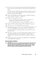
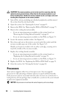
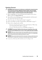
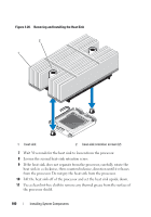
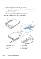
3 If you are adding a processor to an empty socket, perform the following steps: a Remove the protective cover from the processor socket. b Pull the socket-release lever 90 degrees upward. See Figure 3-21. c Lift the processor shield. See Figure 3-21. 4 Install the processor in the socket. NOTICE: Positioning the processor incorrectly can permanently damage the system board or the processor when you turn the system on. a If the release lever on the processor socket is not fully open, move it to that position. b With the processor and the socket keys aligned, set the processor lightly in the socket. NOTICE: Do not use force to seat the processor. When the processor is positioned correctly, it fits easily into the socket. c Close the processor shield. See Figure 3-21. d Rotate the socket release lever back down until it snaps into place, securing the processor. See Figure 3-21. 5 Install the heat sink. NOTE: If you did not receive a replacement heat sink, use the heat sink that you removed in step 10. a If you receive a heat sink and pre-applied thermal grease with your processor kit, remove the protective sheet from the thermal grease layer on top of the heat sink. See Figure 3-20. If you did not receive a replacement heat sink with your processor kit, apply new thermal grease: • Using a clean lint-free cloth, remove the existing thermal grease from the heat sink. • Open the grease packet included with your processor kit and apply thermal grease evenly to the top of the processor. b Place the heat sink onto the processor. See Figure 3-20. c While pressing down on the heat, secure the heat sink by tightening the two retention screws until resistance is felt. See Figure 3-20. 102 Installing System Components
-
 1
1 -
2
-
3
-
4
-
5
-
6
-
7
-
8
-
9
-
10
-
11
-
12
-
13
-
14
-
15
-
16
-
17
-
18
-
19
-
20
-
21
-
22
-
23
-
24
-
25
-
26
-
27
-
28
-
29
-
30
-
31
-
32
-
33
-
34
-
35
-
36
-
37
-
38
-
39
-
40
-
41
-
42
-
43
-
44
-
45
-
46
-
47
-
48
-
49
-
50
-
51
-
52
-
53
-
54
-
55
-
56
-
57
-
58
-
59
-
60
-
61
-
62
-
63
-
64
-
65
-
66
-
67
-
68
-
69
-
70
-
71
-
72
-
73
-
74
-
75
-
76
-
77
-
78
-
79
-
80
-
81
-
82
-
83
-
84
-
85
-
86
-
87
-
88
-
89
-
90
-
91
-
92
-
93
-
94
-
95
-
96
-
 97
97 -
 98
98 -
 99
99 -
 100
100 -
 101
101 -
 102
102 -
 103
103 -
 104
104 -
 105
105 -
 106
106 -
 107
107 -
108
-
109
-
110
-
111
-
112
-
113
-
114
-
115
-
116
-
117
-
118
-
119
-
120
-
121
-
122
-
123
-
124
-
125
-
126
-
127
-
128
-
129
-
130
-
131
-
132
-
133
-
134
-
135
-
136
-
137
-
138
-
139
-
140
-
141
-
142
-
143
-
144
-
145
-
146
-
147
-
148
-
149
-
150
-
151
-
152
-
153
-
154
-
155
-
156
-
157
-
158
-
159
-
160
-
161
-
162
-
163
-
164
-
165
-
166
-
167
-
168
-
169
-
170
-
171
-
172
-
173
-
174
-
175
-
176
-
177
-
178
-
179
-
180
-
181
-
182
-
183
-
184
-
185
-
186
-
187
-
188
-
189
-
190
-
191
-
192
-
193
-
194
-
195
-
196
-
197
-
198
 |
 |