Dell PowerEdge R905 Hardware Owner's Manual (PDF) - Page 92
General Memory Module Installation Guidelines
 |
View all Dell PowerEdge R905 manuals
Add to My Manuals
Save this manual to your list of manuals |
Page 92 highlights
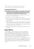
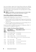
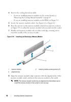
Your system hardware supports Non-Uniform Memory Architecture (NUMA). Each processor has its own memory controller and local memory for reduced access times, but it can also access memory from another processor. This architecture improves system performance if an operating system is installed that supports this feature. NOTICE: To enable NUMA, run the System Setup program and disable the Node Interleaving option. See "Using the System Setup Program" on page 43. General Memory Module Installation Guidelines To ensure optimal performance of your system, observe the following guidelines when configuring your system memory. • Memory modules must be installed in pairs, beginning with the first two sockets in each set of memory modules. These sockets are marked by white retention levers. • All memory modules must be identical in speed and technology. The two memory modules in each pair must be the same size. Memory can either be installed in a two-processor configuration (Table 3-1) or a four-processor configuration (Table 3-2). Table 3-1. Examples of Two-Processor Memory Configurations Total System Memory 2 GB 4 GB 4 GB 6 GB 8 GB 8 GB 16 GB 16 GB Memory Modules - Memory Module Locations Number, Size and Speed Four 512 MB, 667 MHz A1, A2, B1, B2 Four 1 GB, 667 MHz A1, A2, B1, B2 Eight 512 MB, 667 MHz A1, A2, A3, A4, B1, B2, B3, B4 Twelve 512 MB, 667 MHz A1, A2, A3, A4, A5, A6, B1, B2, B3, B4, B5, B6 Four 2 GB, 667 MHz A1, A2, B1, B2 Eight 1 GB, 667 MHz A1, A2, A3, A4, B1, B2, B3, B4 Four 4 GB, 667 MHz A1, A2, B1, B2 Eight 2 GB, 667 MHz A1, A2, A3, A4, B1, B2, B3, B4 92 Installing System Components
-
 1
1 -
2
-
3
-
4
-
5
-
6
-
7
-
8
-
9
-
10
-
11
-
12
-
13
-
14
-
15
-
16
-
17
-
18
-
19
-
20
-
21
-
22
-
23
-
24
-
25
-
26
-
27
-
28
-
29
-
30
-
31
-
32
-
33
-
34
-
35
-
36
-
37
-
38
-
39
-
40
-
41
-
42
-
43
-
44
-
45
-
46
-
47
-
48
-
49
-
50
-
51
-
52
-
53
-
54
-
55
-
56
-
57
-
58
-
59
-
60
-
61
-
62
-
63
-
64
-
65
-
66
-
67
-
68
-
69
-
70
-
71
-
72
-
73
-
74
-
75
-
76
-
77
-
78
-
79
-
80
-
81
-
82
-
83
-
84
-
85
-
86
-
 87
87 -
 88
88 -
 89
89 -
 90
90 -
 91
91 -
 92
92 -
 93
93 -
 94
94 -
 95
95 -
 96
96 -
 97
97 -
98
-
99
-
100
-
101
-
102
-
103
-
104
-
105
-
106
-
107
-
108
-
109
-
110
-
111
-
112
-
113
-
114
-
115
-
116
-
117
-
118
-
119
-
120
-
121
-
122
-
123
-
124
-
125
-
126
-
127
-
128
-
129
-
130
-
131
-
132
-
133
-
134
-
135
-
136
-
137
-
138
-
139
-
140
-
141
-
142
-
143
-
144
-
145
-
146
-
147
-
148
-
149
-
150
-
151
-
152
-
153
-
154
-
155
-
156
-
157
-
158
-
159
-
160
-
161
-
162
-
163
-
164
-
165
-
166
-
167
-
168
-
169
-
170
-
171
-
172
-
173
-
174
-
175
-
176
-
177
-
178
-
179
-
180
-
181
-
182
-
183
-
184
-
185
-
186
-
187
-
188
-
189
-
190
-
191
-
192
-
193
-
194
-
195
-
196
-
197
-
198
 |
 |