Dell PowerEdge R905 Hardware Owner's Manual (PDF) - Page 19
Power Indicator Codes
 |
View all Dell PowerEdge R905 manuals
Add to My Manuals
Save this manual to your list of manuals |
Page 19 highlights
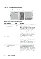
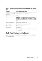
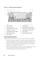
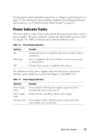
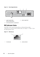
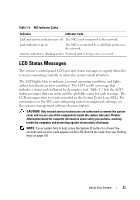
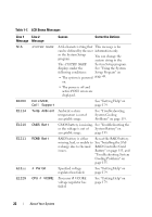
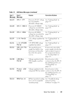
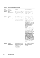
For information about individual connectors, see "Jumpers and Connectors" on page 171. For information about enabling, disabling, and configuring I/O ports and connectors, see "Using the System Setup Program" on page 43. Power Indicator Codes The power button on the front panel controls the power input to the system's power supplies. The power indicator can provide information on power status (see Figure 1-1). Table 1-4 lists the power button indicator codes. Table 1-4. Power Button Indicators Indicator On Flickering Off Function Indicates that power is supplied to the system and the system is operational. Power is supplied to the system but the system is powering up, or shutting down. Indicates that no power is supplied to the system. The indicators on the power supplies show whether power is present or whether a power fault has occurred (see Figure 1-4 and Table 1-5). Table 1-5. Power Supply Indicators Indicator Power supply status Power supply fault AC line status Function Green indicates that the power supply is operational and providing DC power to the system. Amber indicates a problem with the power supply. Green indicates that a valid AC source is connected to the power supply and is operational. About Your System 19
-
 1
1 -
2
-
3
-
4
-
5
-
6
-
7
-
8
-
9
-
10
-
11
-
12
-
13
-
 14
14 -
 15
15 -
 16
16 -
 17
17 -
 18
18 -
 19
19 -
 20
20 -
 21
21 -
 22
22 -
 23
23 -
 24
24 -
25
-
26
-
27
-
28
-
29
-
30
-
31
-
32
-
33
-
34
-
35
-
36
-
37
-
38
-
39
-
40
-
41
-
42
-
43
-
44
-
45
-
46
-
47
-
48
-
49
-
50
-
51
-
52
-
53
-
54
-
55
-
56
-
57
-
58
-
59
-
60
-
61
-
62
-
63
-
64
-
65
-
66
-
67
-
68
-
69
-
70
-
71
-
72
-
73
-
74
-
75
-
76
-
77
-
78
-
79
-
80
-
81
-
82
-
83
-
84
-
85
-
86
-
87
-
88
-
89
-
90
-
91
-
92
-
93
-
94
-
95
-
96
-
97
-
98
-
99
-
100
-
101
-
102
-
103
-
104
-
105
-
106
-
107
-
108
-
109
-
110
-
111
-
112
-
113
-
114
-
115
-
116
-
117
-
118
-
119
-
120
-
121
-
122
-
123
-
124
-
125
-
126
-
127
-
128
-
129
-
130
-
131
-
132
-
133
-
134
-
135
-
136
-
137
-
138
-
139
-
140
-
141
-
142
-
143
-
144
-
145
-
146
-
147
-
148
-
149
-
150
-
151
-
152
-
153
-
154
-
155
-
156
-
157
-
158
-
159
-
160
-
161
-
162
-
163
-
164
-
165
-
166
-
167
-
168
-
169
-
170
-
171
-
172
-
173
-
174
-
175
-
176
-
177
-
178
-
179
-
180
-
181
-
182
-
183
-
184
-
185
-
186
-
187
-
188
-
189
-
190
-
191
-
192
-
193
-
194
-
195
-
196
-
197
-
198
 |
 |