Dell PowerEdge R905 Hardware Owner's Manual (PDF) - Page 129
Replacing a Peripheral Interposer Board
 |
View all Dell PowerEdge R905 manuals
Add to My Manuals
Save this manual to your list of manuals |
Page 129 highlights
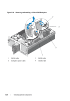
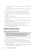
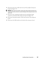
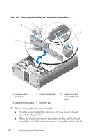
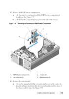
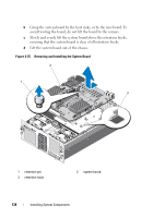
c Lift the board out of the system, being careful to avoid damaging components on the face of the board. d Place the interposer board aside on a work surface. Replacing a Peripheral Interposer Board 1 Install the peripheral interposer board: a Carefully lower the interposer board into the system, being careful to avoid damaging components on the face of the board. See Figure 3-32. b Align the installation alignment slot on the bottom of the interposer board with the alignment pin on the bottom of the chassis. c Slide the retention slots on the interposer board over the retention hooks on the chassis. d Slide the board downward until the blue retention tab snaps into place. 2 Connect the SATA, planar interface, and control panel cables to the back of the interposer board. See Figure 3-32. 3 Connect the power cable to the top of the interposer board. 4 Reconnect the SAS and backplane power cables to the back of the SAS backplane. See Figure 3-30 or Figure 3-31. 5 Replace the cooling shroud assembly. See "Replacing the Cooling Shroud Assembly" on page 70. 6 Replace the PEM. See "Replacing the PEM or PEM Shell" on page 76. 7 Close the system. See "Closing the System" on page 66. 8 Reconnect the system to its electrical outlet and turn the system on, including any attached peripherals. Installing System Components 129
-
 1
1 -
2
-
3
-
4
-
5
-
6
-
7
-
8
-
9
-
10
-
11
-
12
-
13
-
14
-
15
-
16
-
17
-
18
-
19
-
20
-
21
-
22
-
23
-
24
-
25
-
26
-
27
-
28
-
29
-
30
-
31
-
32
-
33
-
34
-
35
-
36
-
37
-
38
-
39
-
40
-
41
-
42
-
43
-
44
-
45
-
46
-
47
-
48
-
49
-
50
-
51
-
52
-
53
-
54
-
55
-
56
-
57
-
58
-
59
-
60
-
61
-
62
-
63
-
64
-
65
-
66
-
67
-
68
-
69
-
70
-
71
-
72
-
73
-
74
-
75
-
76
-
77
-
78
-
79
-
80
-
81
-
82
-
83
-
84
-
85
-
86
-
87
-
88
-
89
-
90
-
91
-
92
-
93
-
94
-
95
-
96
-
97
-
98
-
99
-
100
-
101
-
102
-
103
-
104
-
105
-
106
-
107
-
108
-
109
-
110
-
111
-
112
-
113
-
114
-
115
-
116
-
117
-
118
-
119
-
120
-
121
-
122
-
123
-
 124
124 -
 125
125 -
 126
126 -
 127
127 -
 128
128 -
 129
129 -
 130
130 -
 131
131 -
 132
132 -
 133
133 -
 134
134 -
135
-
136
-
137
-
138
-
139
-
140
-
141
-
142
-
143
-
144
-
145
-
146
-
147
-
148
-
149
-
150
-
151
-
152
-
153
-
154
-
155
-
156
-
157
-
158
-
159
-
160
-
161
-
162
-
163
-
164
-
165
-
166
-
167
-
168
-
169
-
170
-
171
-
172
-
173
-
174
-
175
-
176
-
177
-
178
-
179
-
180
-
181
-
182
-
183
-
184
-
185
-
186
-
187
-
188
-
189
-
190
-
191
-
192
-
193
-
194
-
195
-
196
-
197
-
198
 |
 |