Dell PowerEdge R905 Hardware Owner's Manual (PDF) - Page 175
Processor Expansion Module Board Connectors
 |
View all Dell PowerEdge R905 manuals
Add to My Manuals
Save this manual to your list of manuals |
Page 175 highlights
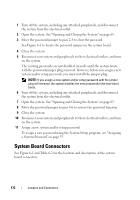
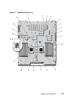
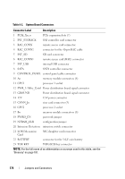
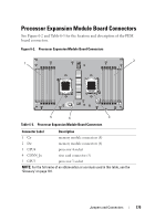
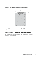
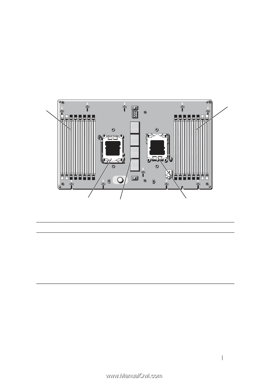
Processor Expansion Module Board Connectors See Figure 6-2 and Table 6-3 for the location and description of the PEM board connectors. Figure 6-2. Processor Expansion Module Board Connectors 2 1 5 4 3 Table 6-3. Processor Expansion Module Board Connectors Connector Label Description 1 Cn memory module connectors (8) 2 Dn memory module connectors (8) 3 CPU4 processor 4 socket 4 CONN_Jn riser card connector (5) 5 CPU3 processor 3 socket NOTE: For the full name of an abbreviation or acronym used in this table, see the "Glossary" on page 181. Jumpers and Connectors 175
-
 1
1 -
2
-
3
-
4
-
5
-
6
-
7
-
8
-
9
-
10
-
11
-
12
-
13
-
14
-
15
-
16
-
17
-
18
-
19
-
20
-
21
-
22
-
23
-
24
-
25
-
26
-
27
-
28
-
29
-
30
-
31
-
32
-
33
-
34
-
35
-
36
-
37
-
38
-
39
-
40
-
41
-
42
-
43
-
44
-
45
-
46
-
47
-
48
-
49
-
50
-
51
-
52
-
53
-
54
-
55
-
56
-
57
-
58
-
59
-
60
-
61
-
62
-
63
-
64
-
65
-
66
-
67
-
68
-
69
-
70
-
71
-
72
-
73
-
74
-
75
-
76
-
77
-
78
-
79
-
80
-
81
-
82
-
83
-
84
-
85
-
86
-
87
-
88
-
89
-
90
-
91
-
92
-
93
-
94
-
95
-
96
-
97
-
98
-
99
-
100
-
101
-
102
-
103
-
104
-
105
-
106
-
107
-
108
-
109
-
110
-
111
-
112
-
113
-
114
-
115
-
116
-
117
-
118
-
119
-
120
-
121
-
122
-
123
-
124
-
125
-
126
-
127
-
128
-
129
-
130
-
131
-
132
-
133
-
134
-
135
-
136
-
137
-
138
-
139
-
140
-
141
-
142
-
143
-
144
-
145
-
146
-
147
-
148
-
149
-
150
-
151
-
152
-
153
-
154
-
155
-
156
-
157
-
158
-
159
-
160
-
161
-
162
-
163
-
164
-
165
-
166
-
167
-
168
-
169
-
 170
170 -
 171
171 -
 172
172 -
 173
173 -
 174
174 -
 175
175 -
 176
176 -
 177
177 -
 178
178 -
 179
179 -
 180
180 -
181
-
182
-
183
-
184
-
185
-
186
-
187
-
188
-
189
-
190
-
191
-
192
-
193
-
194
-
195
-
196
-
197
-
198
 |
 |
Jumpers and Connectors
175
Processor Expansion Module Board Connectors
See Figure 6-2 and Table 6-3 for the location and description of the PEM
board connectors.
Figure 6-2.
Processor Expansion Module Board Connectors
Table 6-3.
Processor Expansion Module Board Connectors
Connector Label
Description
1
C
n
memory module connectors (8)
2
D
n
memory module connectors (8)
3
CPU4
processor 4 socket
4
CONN_J
n
riser card connector (5)
5
CPU3
processor 3 socket
NOTE:
For the full name of an abbreviation or acronym used in this table, see the
"Glossary" on page 181.
3
2
4
5
1