Dell PowerEdge R905 Hardware Owner's Manual (PDF) - Page 70
Replacing the Cooling Shroud Assembly, alignment pins on the system board. See
 |
View all Dell PowerEdge R905 manuals
Add to My Manuals
Save this manual to your list of manuals |
Page 70 highlights
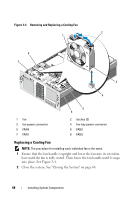
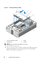
Figure 3-5. Removing and Replacing the Cooling Shroud Assembly 1 2 3 1 cooling shroud assembly 3 alignment pins (4) 2 snaps (4) Replacing the Cooling Shroud Assembly 1 Slowly lower the shroud assembly straight down into the system. The snaps on the four corners of the shroud fit over the four corresponding alignment pins on the system board. See Figure 3-5. 70 Installing System Components
-
 1
1 -
2
-
3
-
4
-
5
-
6
-
7
-
8
-
9
-
10
-
11
-
12
-
13
-
14
-
15
-
16
-
17
-
18
-
19
-
20
-
21
-
22
-
23
-
24
-
25
-
26
-
27
-
28
-
29
-
30
-
31
-
32
-
33
-
34
-
35
-
36
-
37
-
38
-
39
-
40
-
41
-
42
-
43
-
44
-
45
-
46
-
47
-
48
-
49
-
50
-
51
-
52
-
53
-
54
-
55
-
56
-
57
-
58
-
59
-
60
-
61
-
62
-
63
-
64
-
 65
65 -
 66
66 -
 67
67 -
 68
68 -
 69
69 -
 70
70 -
 71
71 -
 72
72 -
 73
73 -
 74
74 -
 75
75 -
76
-
77
-
78
-
79
-
80
-
81
-
82
-
83
-
84
-
85
-
86
-
87
-
88
-
89
-
90
-
91
-
92
-
93
-
94
-
95
-
96
-
97
-
98
-
99
-
100
-
101
-
102
-
103
-
104
-
105
-
106
-
107
-
108
-
109
-
110
-
111
-
112
-
113
-
114
-
115
-
116
-
117
-
118
-
119
-
120
-
121
-
122
-
123
-
124
-
125
-
126
-
127
-
128
-
129
-
130
-
131
-
132
-
133
-
134
-
135
-
136
-
137
-
138
-
139
-
140
-
141
-
142
-
143
-
144
-
145
-
146
-
147
-
148
-
149
-
150
-
151
-
152
-
153
-
154
-
155
-
156
-
157
-
158
-
159
-
160
-
161
-
162
-
163
-
164
-
165
-
166
-
167
-
168
-
169
-
170
-
171
-
172
-
173
-
174
-
175
-
176
-
177
-
178
-
179
-
180
-
181
-
182
-
183
-
184
-
185
-
186
-
187
-
188
-
189
-
190
-
191
-
192
-
193
-
194
-
195
-
196
-
197
-
198
 |
 |
70
Installing System Components
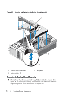
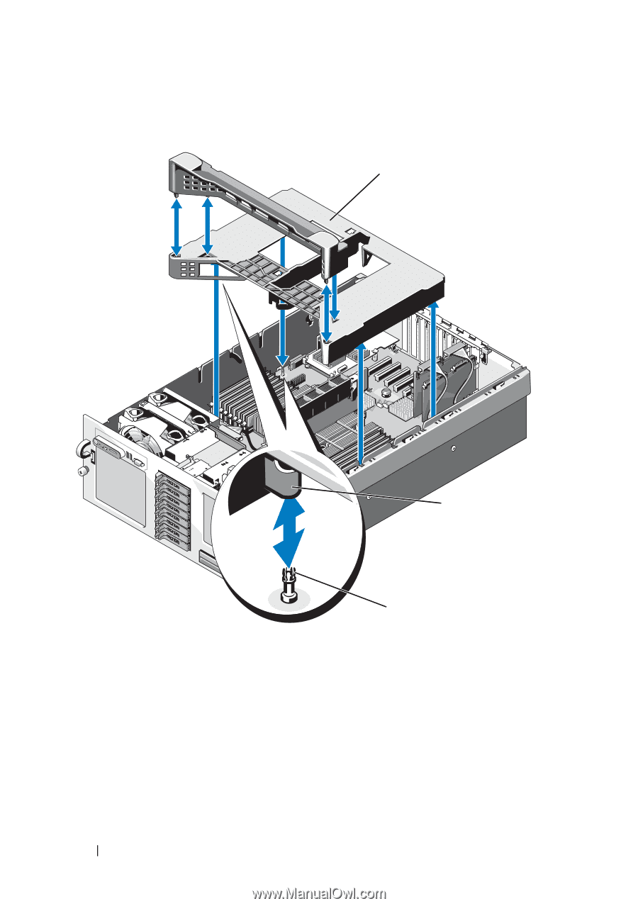
Figure 3-5.
Removing and Replacing the Cooling Shroud Assembly
Replacing the Cooling Shroud Assembly
1
Slowly lower the shroud assembly straight down into the system. The
snaps on the four corners of the shroud fit over the four corresponding
alignment pins on the system board. See Figure 3-5.
1
cooling shroud assembly
2
snaps (4)
3
alignment pins (4)
1
3
2