HP xw8600 HP xw8600 Workstation Service and Technical Reference Guide - Page 115
Connecting the data cable
 |
View all HP xw8600 manuals
Add to My Manuals
Save this manual to your list of manuals |
Page 115 highlights
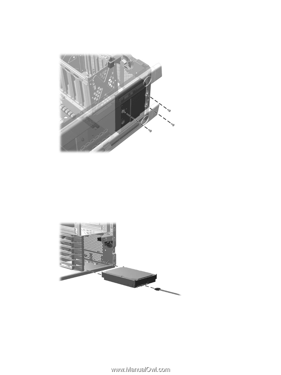
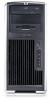
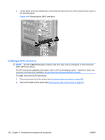
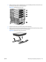
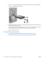
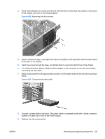
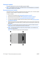
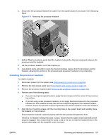
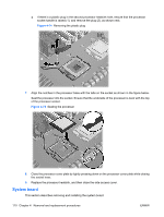
3. Place the workstation on its side and remove the three drive screws that are located on the bottom of the chassis as shown in the following figure. Figure 4-68 Removing the drive screws 4. Insert the drive into bay 5, and align the holes in the bottom of the hard drive with the screw holes at the base of the chassis. 5. Insert the screws through the base, and tighten them to secure the hard drive to the chassis. 6. For a SAS hard drive, attach a SAS-to-SATA adapter to the connector on the hard drive before connecting the data cable. 7. Attach a data cable from the appropriate connector on the system board to the hard drive as shown below. Figure 4-69 Connecting the data cable 8. Connect a power cable to the drive. The power cable is a separate cable with a single connector located in a cable clip in front of the Power Supply. 9. Replace the side access panel. ENWW Removing and replacing components 105
-
 1
1 -
2
-
3
-
4
-
5
-
6
-
7
-
8
-
9
-
10
-
11
-
12
-
13
-
14
-
15
-
16
-
17
-
18
-
19
-
20
-
21
-
22
-
23
-
24
-
25
-
26
-
27
-
28
-
29
-
30
-
31
-
32
-
33
-
34
-
35
-
36
-
37
-
38
-
39
-
40
-
41
-
42
-
43
-
44
-
45
-
46
-
47
-
48
-
49
-
50
-
51
-
52
-
53
-
54
-
55
-
56
-
57
-
58
-
59
-
60
-
61
-
62
-
63
-
64
-
65
-
66
-
67
-
68
-
69
-
70
-
71
-
72
-
73
-
74
-
75
-
76
-
77
-
78
-
79
-
80
-
81
-
82
-
83
-
84
-
85
-
86
-
87
-
88
-
89
-
90
-
91
-
92
-
93
-
94
-
95
-
96
-
97
-
98
-
99
-
100
-
101
-
102
-
103
-
104
-
105
-
106
-
107
-
108
-
109
-
 110
110 -
 111
111 -
 112
112 -
 113
113 -
 114
114 -
 115
115 -
 116
116 -
 117
117 -
 118
118 -
 119
119 -
 120
120 -
121
-
122
-
123
-
124
-
125
-
126
-
127
-
128
-
129
-
130
-
131
-
132
-
133
-
134
-
135
-
136
-
137
-
138
-
139
-
140
-
141
-
142
-
143
-
144
-
145
-
146
-
147
-
148
-
149
-
150
-
151
-
152
-
153
-
154
-
155
-
156
-
157
-
158
-
159
-
160
-
161
-
162
-
163
-
164
-
165
-
166
-
167
-
168
-
169
-
170
-
171
-
172
-
173
-
174
-
175
-
176
-
177
-
178
-
179
-
180
 |
 |