HP xw8600 HP xw8600 Workstation Service and Technical Reference Guide - Page 172
PCI, memory, and rear chassis fan power system board, CPU fan system board connector
 |
View all HP xw8600 manuals
Add to My Manuals
Save this manual to your list of manuals |
Page 172 highlights
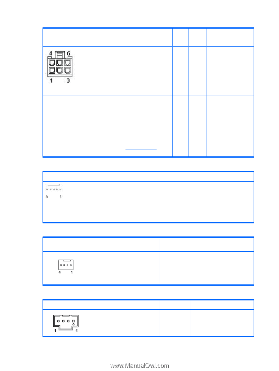
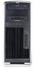
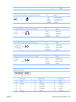
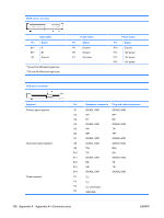
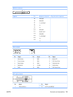
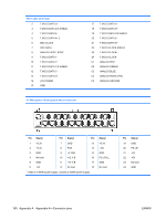
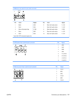
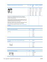
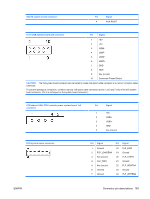
PCI Express auxiliary power 6-pin cable connector Pin Color 800W P16 P17 1050W P16 1050W P17 1 Yellow 12 V-G 12 V-G1 2 Yellow 12 V-G 12 V-G1 3 Yellow 12 V-G 12 V-G1 4 Black GND GND 5 Black GND GND 6 Black GND GND 12 V-G2 12 V-G2 12 V-G2 GND GND GND Verify that you can differentiate between the power cable that connects to the PCI Express x16 card, and the power cable that connects to the system board. These two cables have different pin counts and different colors. The PCI Express power cable has a 6-pin black connector, and the system board power cable has a 4-pin white connector. When power is present, never connect the PCI Express power cable to the system board or the system board can be damaged. For proper PCI card installation information, see PCI Express cards on page 92. CPU fan system board connector Pin Signal 1 GND 2 +12V 3 Tach 1 4 PWM 5 Tach 2 PCI, memory, and rear chassis fan power system board connector Pin Signal 1 Ground 2 +12V 3 Tach 4 PWM AUX IN system board connector 162 Appendix A Appendix A-Connector pins Pin Signal 1 AUX LEFT 2 AGND 3 AGND ENWW
-
 1
1 -
2
-
3
-
4
-
5
-
6
-
7
-
8
-
9
-
10
-
11
-
12
-
13
-
14
-
15
-
16
-
17
-
18
-
19
-
20
-
21
-
22
-
23
-
24
-
25
-
26
-
27
-
28
-
29
-
30
-
31
-
32
-
33
-
34
-
35
-
36
-
37
-
38
-
39
-
40
-
41
-
42
-
43
-
44
-
45
-
46
-
47
-
48
-
49
-
50
-
51
-
52
-
53
-
54
-
55
-
56
-
57
-
58
-
59
-
60
-
61
-
62
-
63
-
64
-
65
-
66
-
67
-
68
-
69
-
70
-
71
-
72
-
73
-
74
-
75
-
76
-
77
-
78
-
79
-
80
-
81
-
82
-
83
-
84
-
85
-
86
-
87
-
88
-
89
-
90
-
91
-
92
-
93
-
94
-
95
-
96
-
97
-
98
-
99
-
100
-
101
-
102
-
103
-
104
-
105
-
106
-
107
-
108
-
109
-
110
-
111
-
112
-
113
-
114
-
115
-
116
-
117
-
118
-
119
-
120
-
121
-
122
-
123
-
124
-
125
-
126
-
127
-
128
-
129
-
130
-
131
-
132
-
133
-
134
-
135
-
136
-
137
-
138
-
139
-
140
-
141
-
142
-
143
-
144
-
145
-
146
-
147
-
148
-
149
-
150
-
151
-
152
-
153
-
154
-
155
-
156
-
157
-
158
-
159
-
160
-
161
-
162
-
163
-
164
-
165
-
166
-
 167
167 -
 168
168 -
 169
169 -
 170
170 -
 171
171 -
 172
172 -
 173
173 -
 174
174 -
 175
175 -
 176
176 -
 177
177 -
178
-
179
-
180
 |
 |