HP xw8600 HP xw8600 Workstation Service and Technical Reference Guide - Page 91
Open all memory slot latches as shown in the following
 |
View all HP xw8600 manuals
Add to My Manuals
Save this manual to your list of manuals |
Page 91 highlights
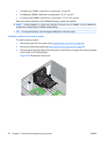
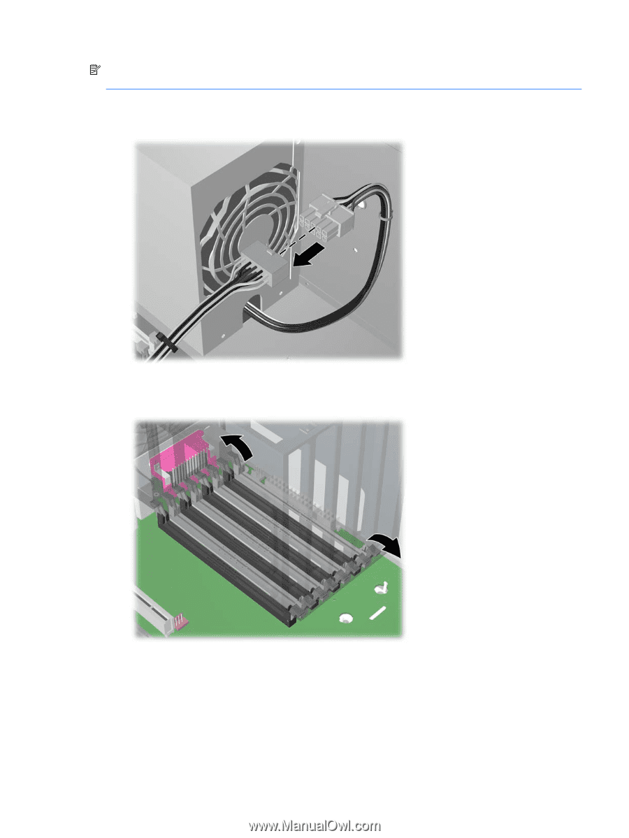
NOTE: All four memory risers must be present with card cage and memory duct assembly properly installed during operation. 1. Connect the memory riser cable to power supply cable P18 as shown in the following figure. Figure 4-34 Connecting the memory riser cable to the power supply cable 2. Open all memory slot latches as shown in the following figure. Figure 4-35 Opening the memory slot latches ENWW Removing and replacing components 81
-
 1
1 -
2
-
3
-
4
-
5
-
6
-
7
-
8
-
9
-
10
-
11
-
12
-
13
-
14
-
15
-
16
-
17
-
18
-
19
-
20
-
21
-
22
-
23
-
24
-
25
-
26
-
27
-
28
-
29
-
30
-
31
-
32
-
33
-
34
-
35
-
36
-
37
-
38
-
39
-
40
-
41
-
42
-
43
-
44
-
45
-
46
-
47
-
48
-
49
-
50
-
51
-
52
-
53
-
54
-
55
-
56
-
57
-
58
-
59
-
60
-
61
-
62
-
63
-
64
-
65
-
66
-
67
-
68
-
69
-
70
-
71
-
72
-
73
-
74
-
75
-
76
-
77
-
78
-
79
-
80
-
81
-
82
-
83
-
84
-
85
-
 86
86 -
 87
87 -
 88
88 -
 89
89 -
 90
90 -
 91
91 -
 92
92 -
 93
93 -
 94
94 -
 95
95 -
 96
96 -
97
-
98
-
99
-
100
-
101
-
102
-
103
-
104
-
105
-
106
-
107
-
108
-
109
-
110
-
111
-
112
-
113
-
114
-
115
-
116
-
117
-
118
-
119
-
120
-
121
-
122
-
123
-
124
-
125
-
126
-
127
-
128
-
129
-
130
-
131
-
132
-
133
-
134
-
135
-
136
-
137
-
138
-
139
-
140
-
141
-
142
-
143
-
144
-
145
-
146
-
147
-
148
-
149
-
150
-
151
-
152
-
153
-
154
-
155
-
156
-
157
-
158
-
159
-
160
-
161
-
162
-
163
-
164
-
165
-
166
-
167
-
168
-
169
-
170
-
171
-
172
-
173
-
174
-
175
-
176
-
177
-
178
-
179
-
180
 |
 |
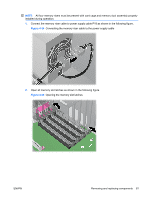
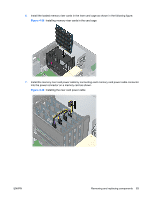
NOTE:
All four memory risers must be present with card cage and memory duct assembly properly
installed during operation.
1.
Connect the memory riser cable to power supply cable P18 as shown in the following figure.
Figure 4-34
Connecting the memory riser cable to the power supply cable
2.
Open all memory slot latches as shown in the following figure.
Figure 4-35
Opening the memory slot latches
ENWW
Removing and replacing components
81