HP xw8600 HP xw8600 Workstation Service and Technical Reference Guide - Page 73
Installing the front panel I/O device assembly, Power button assembly
 |
View all HP xw8600 manuals
Add to My Manuals
Save this manual to your list of manuals |
Page 73 highlights
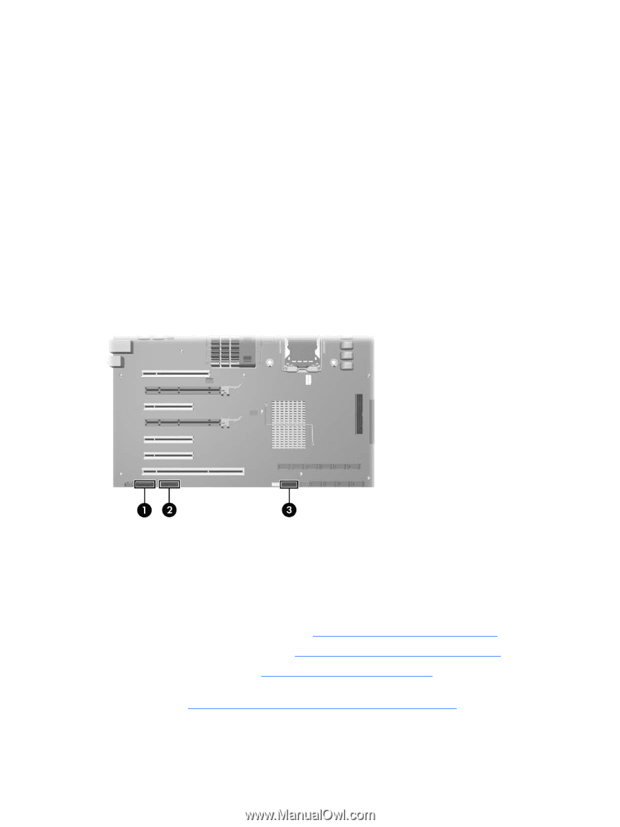
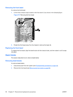
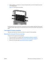
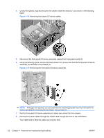
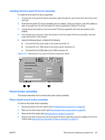
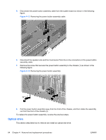
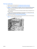
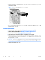
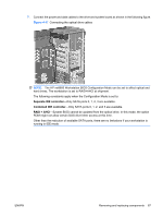
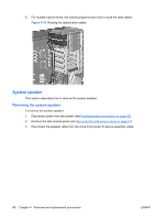
Installing the front panel I/O device assembly To instal the front panel I/O device assembly: 1. Thread each front panel I/O device assembly cable through the same holes from which they were removed. 2. Push the front panel I/O device assembly into the chassis. Using your fingers, orient the cables so there is enough room for the front panel I/O device assembly to easily fit in its slot. 3. Loosely place the bracket on the front panel I/O device assembly and hook the bracket to the chassis. 4. If the bracket was removed, screw the bracket to the front panel I/O device assembly, and then screw the bracket to the chassis. 5. Using the following figure, complete the following: a. Connect the front audio cable to the audio connector (1). b. Connect the front 1394 cable to the control panel connector (2). c. Connect the front USB cable to the USB connector (3). Figure 4-12 Attaching the front panel I/O device assembly cables Power button assembly This section describes how to remove the power button assembly. Removing the power button assembly To remove the power button assembly: 1. Disconnect power from the system (see Predisassembly procedures on page 52). 2. Remove the side access panel (see Removing the side access panel on page 57). 3. Remove the front bezel (see Removing the front bezel on page 60). 4. Remove the three screws from the front panel I/O device assembly and pull it slightly out from the chassis (see Removing the front panel I/O device assembly on page 61). ENWW Removing and replacing components 63
-
 1
1 -
2
-
3
-
4
-
5
-
6
-
7
-
8
-
9
-
10
-
11
-
12
-
13
-
14
-
15
-
16
-
17
-
18
-
19
-
20
-
21
-
22
-
23
-
24
-
25
-
26
-
27
-
28
-
29
-
30
-
31
-
32
-
33
-
34
-
35
-
36
-
37
-
38
-
39
-
40
-
41
-
42
-
43
-
44
-
45
-
46
-
47
-
48
-
49
-
50
-
51
-
52
-
53
-
54
-
55
-
56
-
57
-
58
-
59
-
60
-
61
-
62
-
63
-
64
-
65
-
66
-
67
-
 68
68 -
 69
69 -
 70
70 -
 71
71 -
 72
72 -
 73
73 -
 74
74 -
 75
75 -
 76
76 -
 77
77 -
 78
78 -
79
-
80
-
81
-
82
-
83
-
84
-
85
-
86
-
87
-
88
-
89
-
90
-
91
-
92
-
93
-
94
-
95
-
96
-
97
-
98
-
99
-
100
-
101
-
102
-
103
-
104
-
105
-
106
-
107
-
108
-
109
-
110
-
111
-
112
-
113
-
114
-
115
-
116
-
117
-
118
-
119
-
120
-
121
-
122
-
123
-
124
-
125
-
126
-
127
-
128
-
129
-
130
-
131
-
132
-
133
-
134
-
135
-
136
-
137
-
138
-
139
-
140
-
141
-
142
-
143
-
144
-
145
-
146
-
147
-
148
-
149
-
150
-
151
-
152
-
153
-
154
-
155
-
156
-
157
-
158
-
159
-
160
-
161
-
162
-
163
-
164
-
165
-
166
-
167
-
168
-
169
-
170
-
171
-
172
-
173
-
174
-
175
-
176
-
177
-
178
-
179
-
180
 |
 |