HP xw8600 HP xw8600 Workstation Service and Technical Reference Guide - Page 87
Memory riser assembly,
 |
View all HP xw8600 manuals
Add to My Manuals
Save this manual to your list of manuals |
Page 87 highlights
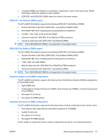
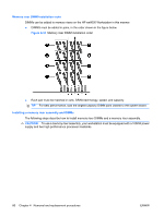
4. Push gently outward on the socket levers as shown in the following figure. Figure 4-27 Opening the DIMM socket levers 5. Align the DIMM connector key with the DIMM socket key, and then seat the DIMM firmly in the socket (1) as shown in the following figure. NOTE: Note the keyed slot about midway across the bottom of the DIMM in the figure below. Figure 4-28 Installing a memory module 6. Secure the socket levers (2). 7. Lower the memory fan until it snaps into place. NOTE: Ensure that all cables are clear of the fan housing when you lower the fan. Memory riser assembly This section presents configuration and removal/installation information for the memory riser assembly. ENWW Removing and replacing components 77
-
 1
1 -
2
-
3
-
4
-
5
-
6
-
7
-
8
-
9
-
10
-
11
-
12
-
13
-
14
-
15
-
16
-
17
-
18
-
19
-
20
-
21
-
22
-
23
-
24
-
25
-
26
-
27
-
28
-
29
-
30
-
31
-
32
-
33
-
34
-
35
-
36
-
37
-
38
-
39
-
40
-
41
-
42
-
43
-
44
-
45
-
46
-
47
-
48
-
49
-
50
-
51
-
52
-
53
-
54
-
55
-
56
-
57
-
58
-
59
-
60
-
61
-
62
-
63
-
64
-
65
-
66
-
67
-
68
-
69
-
70
-
71
-
72
-
73
-
74
-
75
-
76
-
77
-
78
-
79
-
80
-
81
-
 82
82 -
 83
83 -
 84
84 -
 85
85 -
 86
86 -
 87
87 -
 88
88 -
 89
89 -
 90
90 -
 91
91 -
 92
92 -
93
-
94
-
95
-
96
-
97
-
98
-
99
-
100
-
101
-
102
-
103
-
104
-
105
-
106
-
107
-
108
-
109
-
110
-
111
-
112
-
113
-
114
-
115
-
116
-
117
-
118
-
119
-
120
-
121
-
122
-
123
-
124
-
125
-
126
-
127
-
128
-
129
-
130
-
131
-
132
-
133
-
134
-
135
-
136
-
137
-
138
-
139
-
140
-
141
-
142
-
143
-
144
-
145
-
146
-
147
-
148
-
149
-
150
-
151
-
152
-
153
-
154
-
155
-
156
-
157
-
158
-
159
-
160
-
161
-
162
-
163
-
164
-
165
-
166
-
167
-
168
-
169
-
170
-
171
-
172
-
173
-
174
-
175
-
176
-
177
-
178
-
179
-
180
 |
 |
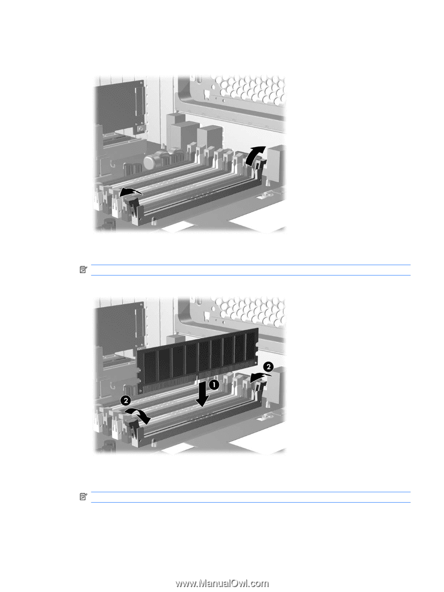
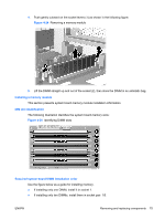
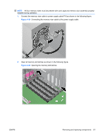
4.
Push gently outward on the socket levers as shown in the following figure.
Figure 4-27
Opening the DIMM socket levers
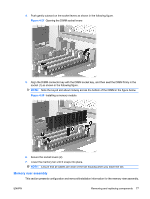
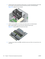
5.
Align the DIMM connector key with the DIMM socket key, and then seat the DIMM firmly in the
socket (1) as shown in the following figure.
NOTE:
Note the keyed slot about midway across the bottom of the DIMM in the figure below.
Figure 4-28
Installing a memory module
6.
Secure the socket levers (2).
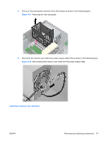
7.
Lower the memory fan until it snaps into place.
NOTE:
Ensure that all cables are clear of the fan housing when you lower the fan.
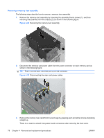
Memory riser assembly
This section presents configuration and removal/installation information for the memory riser assembly.
ENWW
Removing and replacing components
77