HP xw8600 HP xw8600 Workstation Service and Technical Reference Guide - Page 97
number of connectors attached.
 |
View all HP xw8600 manuals
Add to My Manuals
Save this manual to your list of manuals |
Page 97 highlights
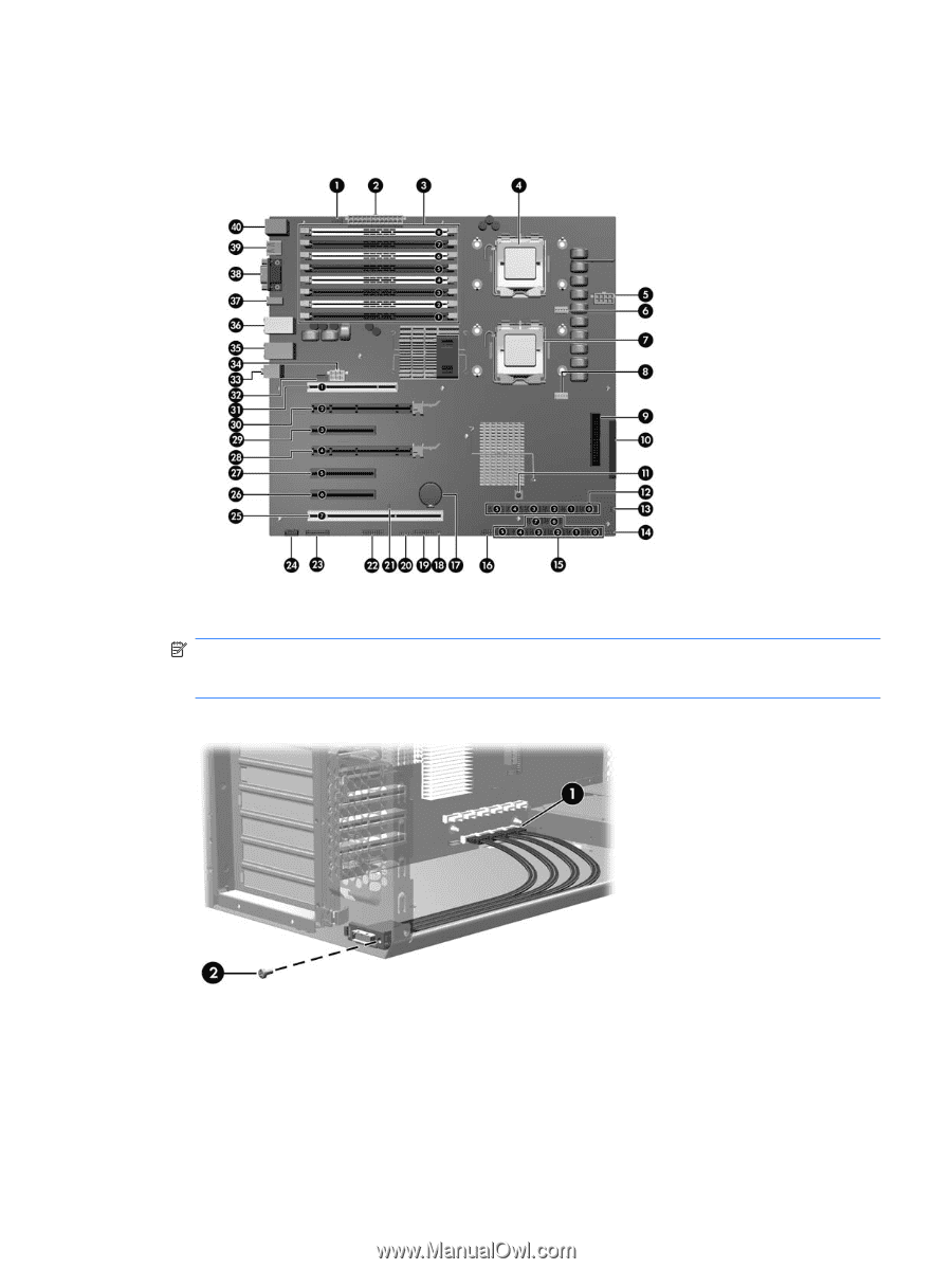
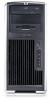
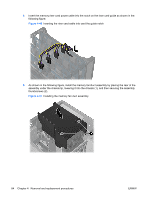
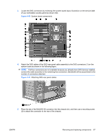
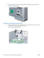
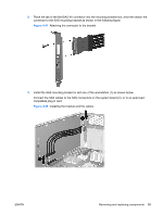
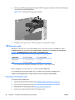
3. Locate the SAS connectors by reviewing the system board layout illustration on the service label of your workstation access panel as shown next. Figure 4-43 System board components 4. Attach the SAS cables of the SAS rear panel cable assembly to the SAS connectors (1) on the system board as shown in the following figure. NOTE: If all four connectors are not available because you already have SAS devices installed, connect the cable assembly to the remaining free connectors. Bandwidth will be proportional to the number of connectors attached. Figure 4-44 Attaching SAS rear panel cables 5. Place the tab of the MiniSAS 4X connector into the chassis slot, and then use a mounting screw (2) to attach the connector to the rear of the chassis. ENWW Removing and replacing components 87
-
 1
1 -
2
-
3
-
4
-
5
-
6
-
7
-
8
-
9
-
10
-
11
-
12
-
13
-
14
-
15
-
16
-
17
-
18
-
19
-
20
-
21
-
22
-
23
-
24
-
25
-
26
-
27
-
28
-
29
-
30
-
31
-
32
-
33
-
34
-
35
-
36
-
37
-
38
-
39
-
40
-
41
-
42
-
43
-
44
-
45
-
46
-
47
-
48
-
49
-
50
-
51
-
52
-
53
-
54
-
55
-
56
-
57
-
58
-
59
-
60
-
61
-
62
-
63
-
64
-
65
-
66
-
67
-
68
-
69
-
70
-
71
-
72
-
73
-
74
-
75
-
76
-
77
-
78
-
79
-
80
-
81
-
82
-
83
-
84
-
85
-
86
-
87
-
88
-
89
-
90
-
91
-
 92
92 -
 93
93 -
 94
94 -
 95
95 -
 96
96 -
 97
97 -
 98
98 -
 99
99 -
 100
100 -
 101
101 -
 102
102 -
103
-
104
-
105
-
106
-
107
-
108
-
109
-
110
-
111
-
112
-
113
-
114
-
115
-
116
-
117
-
118
-
119
-
120
-
121
-
122
-
123
-
124
-
125
-
126
-
127
-
128
-
129
-
130
-
131
-
132
-
133
-
134
-
135
-
136
-
137
-
138
-
139
-
140
-
141
-
142
-
143
-
144
-
145
-
146
-
147
-
148
-
149
-
150
-
151
-
152
-
153
-
154
-
155
-
156
-
157
-
158
-
159
-
160
-
161
-
162
-
163
-
164
-
165
-
166
-
167
-
168
-
169
-
170
-
171
-
172
-
173
-
174
-
175
-
176
-
177
-
178
-
179
-
180
 |
 |