HP xw8600 HP xw8600 Workstation Service and Technical Reference Guide - Page 118
System processor, Removing a system processor
 |
View all HP xw8600 manuals
Add to My Manuals
Save this manual to your list of manuals |
Page 118 highlights
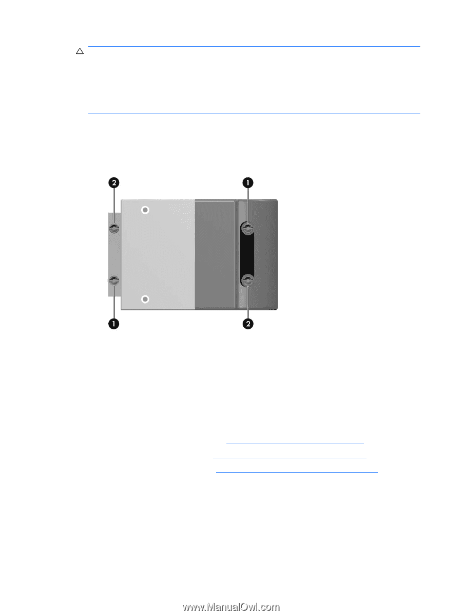
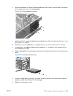
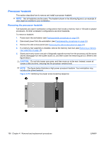
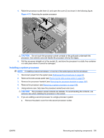
CAUTION: If a second heatsink is installed, do not pinch the processor 1 heatsink fan wire under the processor 2 heatsink. Do not overtighten the heatsink screws. If you overtighten them, you might strip the threads in the system board tray. Do not fully tighten one screw and then move on to the next. Instead, tighten all screws a little at a time, ensuring that the processor remains level. 6. Tighten all screws partially so the processor heatsink remains level. 7. Tighten each set of diagonally opposed screws a little at a time to 6 in.-lbs. of torque as shown in the following illustration. Figure 4-72 Identifying the proper screw tightening sequence 8. Connect the processor heatsink fan connector to the system board. 9. Replace the memory riser duct, if necessary, and then replace the side access cover. System processor This section describes how to remove and install a system processor. Removing a system processor 1. Disconnect power from the system (see Predisassembly procedures on page 52). 2. Remove the side access panel (see Removing the side access panel on page 57). 3. Remove the processor heatsink (see Removing the processor heatsink on page 106). 108 Chapter 4 Removal and replacement procedures ENWW
-
 1
1 -
2
-
3
-
4
-
5
-
6
-
7
-
8
-
9
-
10
-
11
-
12
-
13
-
14
-
15
-
16
-
17
-
18
-
19
-
20
-
21
-
22
-
23
-
24
-
25
-
26
-
27
-
28
-
29
-
30
-
31
-
32
-
33
-
34
-
35
-
36
-
37
-
38
-
39
-
40
-
41
-
42
-
43
-
44
-
45
-
46
-
47
-
48
-
49
-
50
-
51
-
52
-
53
-
54
-
55
-
56
-
57
-
58
-
59
-
60
-
61
-
62
-
63
-
64
-
65
-
66
-
67
-
68
-
69
-
70
-
71
-
72
-
73
-
74
-
75
-
76
-
77
-
78
-
79
-
80
-
81
-
82
-
83
-
84
-
85
-
86
-
87
-
88
-
89
-
90
-
91
-
92
-
93
-
94
-
95
-
96
-
97
-
98
-
99
-
100
-
101
-
102
-
103
-
104
-
105
-
106
-
107
-
108
-
109
-
110
-
111
-
112
-
 113
113 -
 114
114 -
 115
115 -
 116
116 -
 117
117 -
 118
118 -
 119
119 -
 120
120 -
 121
121 -
 122
122 -
 123
123 -
124
-
125
-
126
-
127
-
128
-
129
-
130
-
131
-
132
-
133
-
134
-
135
-
136
-
137
-
138
-
139
-
140
-
141
-
142
-
143
-
144
-
145
-
146
-
147
-
148
-
149
-
150
-
151
-
152
-
153
-
154
-
155
-
156
-
157
-
158
-
159
-
160
-
161
-
162
-
163
-
164
-
165
-
166
-
167
-
168
-
169
-
170
-
171
-
172
-
173
-
174
-
175
-
176
-
177
-
178
-
179
-
180
 |
 |