HP xw8600 HP xw8600 Workstation Service and Technical Reference Guide - Page 76
Installing an optical drive, CAUTION
 |
View all HP xw8600 manuals
Add to My Manuals
Save this manual to your list of manuals |
Page 76 highlights
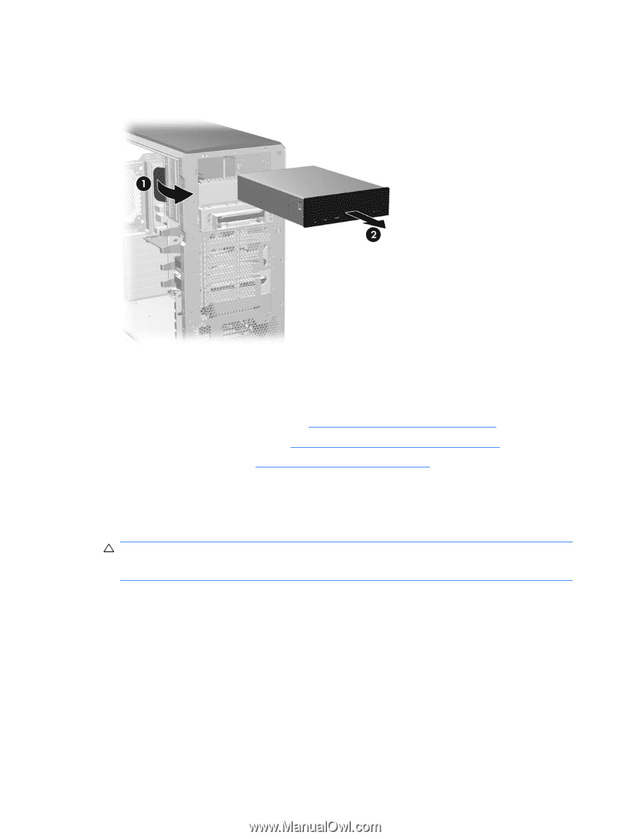
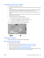
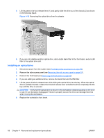
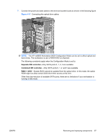
5. Lift the green drive-lock release lever (1) and gently slide the drive out of the chassis (2) as shown in the following figure. Figure 4-16 Removing the optical drive from the chassis 6. If you are not installing another optical drive, add a bezel blank filler to the front bezel, and an EMI filler to the optical drive slot. Installing an optical drive 1. Disconnect power from the system (see Predisassembly procedures on page 52). 2. Remove the side access panel (see Removing the side access panel on page 57). 3. Remove the front bezel (see Removing the front bezel on page 60). 4. If you are adding an additional drive, remove the blank filler and the EMI filler. 5. Lift the green drivelock release lever while sliding the optical drive into the bay. When the optical drive is partially inserted, release the drivelock release lever and slide the drive completely into the bay until the drive is secured. CAUTION: Verify that the optical drive is secure in the workstation chassis by pulling on the drive to see if it can be easily disengaged. Failure to properly secure the drive can damage the drive when moving the workstation. 6. Replace the workstation front bezel. 66 Chapter 4 Removal and replacement procedures ENWW
-
 1
1 -
2
-
3
-
4
-
5
-
6
-
7
-
8
-
9
-
10
-
11
-
12
-
13
-
14
-
15
-
16
-
17
-
18
-
19
-
20
-
21
-
22
-
23
-
24
-
25
-
26
-
27
-
28
-
29
-
30
-
31
-
32
-
33
-
34
-
35
-
36
-
37
-
38
-
39
-
40
-
41
-
42
-
43
-
44
-
45
-
46
-
47
-
48
-
49
-
50
-
51
-
52
-
53
-
54
-
55
-
56
-
57
-
58
-
59
-
60
-
61
-
62
-
63
-
64
-
65
-
66
-
67
-
68
-
69
-
70
-
 71
71 -
 72
72 -
 73
73 -
 74
74 -
 75
75 -
 76
76 -
 77
77 -
 78
78 -
 79
79 -
 80
80 -
 81
81 -
82
-
83
-
84
-
85
-
86
-
87
-
88
-
89
-
90
-
91
-
92
-
93
-
94
-
95
-
96
-
97
-
98
-
99
-
100
-
101
-
102
-
103
-
104
-
105
-
106
-
107
-
108
-
109
-
110
-
111
-
112
-
113
-
114
-
115
-
116
-
117
-
118
-
119
-
120
-
121
-
122
-
123
-
124
-
125
-
126
-
127
-
128
-
129
-
130
-
131
-
132
-
133
-
134
-
135
-
136
-
137
-
138
-
139
-
140
-
141
-
142
-
143
-
144
-
145
-
146
-
147
-
148
-
149
-
150
-
151
-
152
-
153
-
154
-
155
-
156
-
157
-
158
-
159
-
160
-
161
-
162
-
163
-
164
-
165
-
166
-
167
-
168
-
169
-
170
-
171
-
172
-
173
-
174
-
175
-
176
-
177
-
178
-
179
-
180
 |
 |