HP xw8600 HP xw8600 Workstation Service and Technical Reference Guide - Page 96
Slot lane redirection, Card configuration restrictions for power supplies
 |
View all HP xw8600 manuals
Add to My Manuals
Save this manual to your list of manuals |
Page 96 highlights
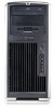
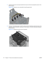
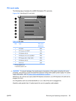
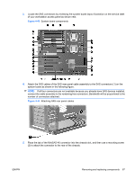
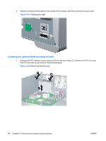
Slot lane redirection The workstation BIOS enables you to determine lane allocation for slots four and five. In the F10 (Setup) Utility, under Advanced>Chipset/Memory>PCIe Lane Allocation, you can select these lane allocations for slots four and five: ● Auto-Automatic mode selection ● x16:x1-Slot 4 runs in x16 mode and slot 5 runs in x1 mode ● x8:x8-Slot 4 runs in x8 mode and slot 5 runs in x8 mode This feature offers optimum throughput automatically to your cards. For automatic lane reallocation, select Auto. When this option is selected, the workstation automatically re-allocates eight lanes from slot four to slot five when a PCI-Express card less than x16 is inserted in slot four. Inserting an x16 card in Slot four configures Slot four to an x16 mode, and Slot five to an x1 mode To review the specific BIOS selections, refer to the Advanced and Device Options settings in The Computer Setup (F10) Utility menu on page 25. Card configuration restrictions for power supplies CAUTION: To prevent damage, the overall power consumption of the system (including I/O cards, processor, and memory) must not exceed the maximum rating of the system power supply. For power supply information, see Power supply specifications on page 8. The maximum graphics configuration with an 800W power supply can include two 75-watt cards (one in slot two, one in slot four), or one 175-watt card in slot two or slot four. If a graphics card greater than 75 watts is used, leave the adjacent slot empty and follow any additional workstation configuration restrictions. The maximum graphics configuration with a 1050W power supply can include up to two 175-watt cards in slots two and four. If a graphics card greater than 75 watts is used, leave the adjacent slot empty. The maximum graphics power is dependent on processor and memory selections. Follow any additional workstation configuration restrictions. SAS rear panel cable (optional) This section describes how to install a SAS rear panel cable and the optional mounting bracket in your workstation. Refer to http://www.hp.com/accessories/workstationsfor information on approved, compatible cards. Installing the SAS rear panel cable To install the SAS rear panel cable: 1. Disconnect power from the system (see Predisassembly procedures on page 52). 2. Remove the side access panel (see Removing the side access panel on page 57). 86 Chapter 4 Removal and replacement procedures ENWW
-
 1
1 -
2
-
3
-
4
-
5
-
6
-
7
-
8
-
9
-
10
-
11
-
12
-
13
-
14
-
15
-
16
-
17
-
18
-
19
-
20
-
21
-
22
-
23
-
24
-
25
-
26
-
27
-
28
-
29
-
30
-
31
-
32
-
33
-
34
-
35
-
36
-
37
-
38
-
39
-
40
-
41
-
42
-
43
-
44
-
45
-
46
-
47
-
48
-
49
-
50
-
51
-
52
-
53
-
54
-
55
-
56
-
57
-
58
-
59
-
60
-
61
-
62
-
63
-
64
-
65
-
66
-
67
-
68
-
69
-
70
-
71
-
72
-
73
-
74
-
75
-
76
-
77
-
78
-
79
-
80
-
81
-
82
-
83
-
84
-
85
-
86
-
87
-
88
-
89
-
90
-
 91
91 -
 92
92 -
 93
93 -
 94
94 -
 95
95 -
 96
96 -
 97
97 -
 98
98 -
 99
99 -
 100
100 -
 101
101 -
102
-
103
-
104
-
105
-
106
-
107
-
108
-
109
-
110
-
111
-
112
-
113
-
114
-
115
-
116
-
117
-
118
-
119
-
120
-
121
-
122
-
123
-
124
-
125
-
126
-
127
-
128
-
129
-
130
-
131
-
132
-
133
-
134
-
135
-
136
-
137
-
138
-
139
-
140
-
141
-
142
-
143
-
144
-
145
-
146
-
147
-
148
-
149
-
150
-
151
-
152
-
153
-
154
-
155
-
156
-
157
-
158
-
159
-
160
-
161
-
162
-
163
-
164
-
165
-
166
-
167
-
168
-
169
-
170
-
171
-
172
-
173
-
174
-
175
-
176
-
177
-
178
-
179
-
180
 |
 |