HP xw8600 HP xw8600 Workstation Service and Technical Reference Guide - Page 81
Power connections to system components, System and memory fan assembly, - memory power
 |
View all HP xw8600 manuals
Add to My Manuals
Save this manual to your list of manuals |
Page 81 highlights
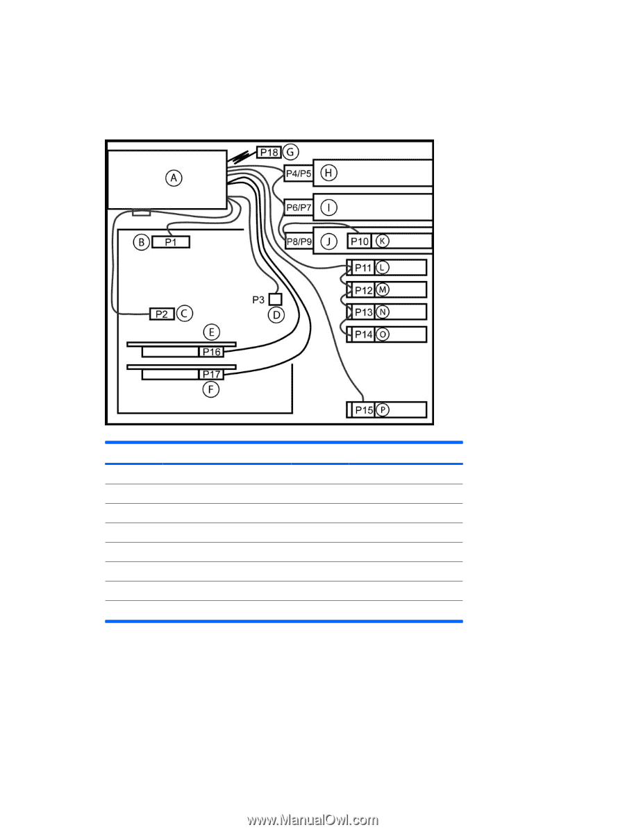
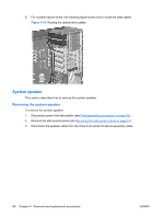
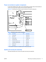
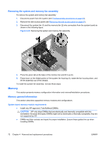
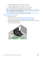
Power connections to system components For help with identifying power cables, see the following figure and table. Ensure that all cables are routed or tied so they cannot interfere with the processor heatsink fans. Figure 4-21 Identifying the workstation power connectors for a typical configuration Table 4-5 Workstation power connector description Item Description Item Description A Power supply I Optical drive B Main power J Optical drive C Memory power K Diskette drive D Processor power L Hard drive E PCI Express auxiliary power M Hard drive F PCI Express auxiliary power N Hard drive G Memory riser* O Hard drive H Optical drive P Hard drive * This connector is included only on workstations with the 1050-watt power supply. System and memory fan assembly This section describes how to remove the system and memory fan assembly. ENWW Removing and replacing components 71
-
 1
1 -
2
-
3
-
4
-
5
-
6
-
7
-
8
-
9
-
10
-
11
-
12
-
13
-
14
-
15
-
16
-
17
-
18
-
19
-
20
-
21
-
22
-
23
-
24
-
25
-
26
-
27
-
28
-
29
-
30
-
31
-
32
-
33
-
34
-
35
-
36
-
37
-
38
-
39
-
40
-
41
-
42
-
43
-
44
-
45
-
46
-
47
-
48
-
49
-
50
-
51
-
52
-
53
-
54
-
55
-
56
-
57
-
58
-
59
-
60
-
61
-
62
-
63
-
64
-
65
-
66
-
67
-
68
-
69
-
70
-
71
-
72
-
73
-
74
-
75
-
 76
76 -
 77
77 -
 78
78 -
 79
79 -
 80
80 -
 81
81 -
 82
82 -
 83
83 -
 84
84 -
 85
85 -
 86
86 -
87
-
88
-
89
-
90
-
91
-
92
-
93
-
94
-
95
-
96
-
97
-
98
-
99
-
100
-
101
-
102
-
103
-
104
-
105
-
106
-
107
-
108
-
109
-
110
-
111
-
112
-
113
-
114
-
115
-
116
-
117
-
118
-
119
-
120
-
121
-
122
-
123
-
124
-
125
-
126
-
127
-
128
-
129
-
130
-
131
-
132
-
133
-
134
-
135
-
136
-
137
-
138
-
139
-
140
-
141
-
142
-
143
-
144
-
145
-
146
-
147
-
148
-
149
-
150
-
151
-
152
-
153
-
154
-
155
-
156
-
157
-
158
-
159
-
160
-
161
-
162
-
163
-
164
-
165
-
166
-
167
-
168
-
169
-
170
-
171
-
172
-
173
-
174
-
175
-
176
-
177
-
178
-
179
-
180
 |
 |