HP xw8600 HP xw8600 Workstation Service and Technical Reference Guide - Page 6

DDR2-667 Fully Buffered DIMM support - memory

Page 6 highlights

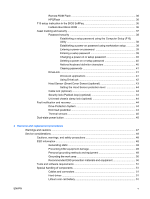
Customer Self-Repair ...52 Predisassembly procedures ...52 System board components ...52 Removing and replacing components 53 Disassembly order ...53 Security lock (Padlock loop) (optional 55 Removing the security lock 55 Cable lock (optional) ...55 Removing the cable lock 56 Universal chassis clamp lock (optional 56 Removing the chassis clamp lock 56 Side access panel ...57 Removing the side access panel 57 Replacing the side access panel 58 Hood Sensor (Smart Cover Sensor) (optional 58 Removing the Hood Sensor 58 Front bezel ...59 Removing the front bezel 60 Replacing the front bezel 60 Bezel blanks ...60 Removing bezel blanks 60 Front panel I/O device assembly 61 Removing the front panel I/O device assembly 61 Installing the front panel I/O device assembly 63 Power button assembly ...63 Removing the power button assembly 63 Optical drive ...64 Removing an optical drive 65 Installing an optical drive 66 System speaker ...68 Removing the system speaker 68 Power supply ...69 Removing the power supply 69 Installing the power supply 70 Power connections to system components 71 System and memory fan assembly 71 Removing the system and memory fan assembly 72 Memory ...72 Memory general information 72 System board memory module requirements 72 DDR2-667 Fully Buffered DIMM support 73 DDR2-800 Fully Buffered DIMM support 73 Supported system board DIMM configurations 73 Supported memory riser DIMM configurations 73 vi ENWW

  • 1
  • 2
  • 3
  • 4
  • 5
  • 6
  • 7
  • 8
  • 9
  • 10
  • 11
  • 12
  • 13
  • 14
  • 15
  • 16
  • 17
  • 18
  • 19
  • 20
  • 21
  • 22
  • 23
  • 24
  • 25
  • 26
  • 27
  • 28
  • 29
  • 30
  • 31
  • 32
  • 33
  • 34
  • 35
  • 36
  • 37
  • 38
  • 39
  • 40
  • 41
  • 42
  • 43
  • 44
  • 45
  • 46
  • 47
  • 48
  • 49
  • 50
  • 51
  • 52
  • 53
  • 54
  • 55
  • 56
  • 57
  • 58
  • 59
  • 60
  • 61
  • 62
  • 63
  • 64
  • 65
  • 66
  • 67
  • 68
  • 69
  • 70
  • 71
  • 72
  • 73
  • 74
  • 75
  • 76
  • 77
  • 78
  • 79
  • 80
  • 81
  • 82
  • 83
  • 84
  • 85
  • 86
  • 87
  • 88
  • 89
  • 90
  • 91
  • 92
  • 93
  • 94
  • 95
  • 96
  • 97
  • 98
  • 99
  • 100
  • 101
  • 102
  • 103
  • 104
  • 105
  • 106
  • 107
  • 108
  • 109
  • 110
  • 111
  • 112
  • 113
  • 114
  • 115
  • 116
  • 117
  • 118
  • 119
  • 120
  • 121
  • 122
  • 123
  • 124
  • 125
  • 126
  • 127
  • 128
  • 129
  • 130
  • 131
  • 132
  • 133
  • 134
  • 135
  • 136
  • 137
  • 138
  • 139
  • 140
  • 141
  • 142
  • 143
  • 144
  • 145
  • 146
  • 147
  • 148
  • 149
  • 150
  • 151
  • 152
  • 153
  • 154
  • 155
  • 156
  • 157
  • 158
  • 159
  • 160
  • 161
  • 162
  • 163
  • 164
  • 165
  • 166
  • 167
  • 168
  • 169
  • 170
  • 171
  • 172
  • 173
  • 174
  • 175
  • 176
  • 177
  • 178
  • 179
  • 180

Customer Self-Repair
.........................................................................................................................
52
Predisassembly procedures
...............................................................................................................
52
System board components
.................................................................................................................
52
Removing and replacing components
................................................................................................
53
Disassembly order
.............................................................................................................
53
Security lock (Padlock loop) (optional)
..............................................................................
55
Removing the security lock
...............................................................................
55
Cable lock (optional)
..........................................................................................................
55
Removing the cable lock
...................................................................................
56
Universal chassis clamp lock (optional)
.............................................................................
56
Removing the chassis clamp lock
.....................................................................
56
Side access panel
..............................................................................................................
57
Removing the side access panel
......................................................................
57
Replacing the side access panel
.......................................................................
58
Hood Sensor (Smart Cover Sensor) (optional)
..................................................................
58
Removing the Hood Sensor
..............................................................................
58
Front bezel
.........................................................................................................................
59
Removing the front bezel
..................................................................................
60
Replacing the front bezel
..................................................................................
60
Bezel blanks
......................................................................................................................
60
Removing bezel blanks
.....................................................................................
60
Front panel I/O device assembly
.......................................................................................
61
Removing the front panel I/O device assembly
.................................................
61
Installing the front panel I/O device assembly
...................................................
63
Power button assembly
.....................................................................................................
63
Removing the power button assembly
..............................................................
63
Optical drive
.......................................................................................................................
64
Removing an optical drive
.................................................................................
65
Installing an optical drive
...................................................................................
66
System speaker
.................................................................................................................
68
Removing the system speaker
..........................................................................
68
Power supply
.....................................................................................................................
69
Removing the power supply
..............................................................................
69
Installing the power supply
................................................................................
70
Power connections to system components
.......................................................................
71
System and memory fan assembly
....................................................................................
71
Removing the system and memory fan assembly
............................................
72
Memory
..............................................................................................................................
72
Memory general information
.............................................................................
72
System board memory module requirements
...................................
72
DDR2-667 Fully Buffered DIMM support
..........................................
73
DDR2-800 Fully Buffered DIMM support
..........................................
73
Supported system board DIMM configurations
................................
73
Supported memory riser DIMM configurations
.................................
73
vi
ENWW