HP xw8600 HP xw8600 Workstation Service and Technical Reference Guide - Page 82
Removing the system and memory fan assembly, Memory, Memory general information
 |
View all HP xw8600 manuals
Add to My Manuals
Save this manual to your list of manuals |
Page 82 highlights
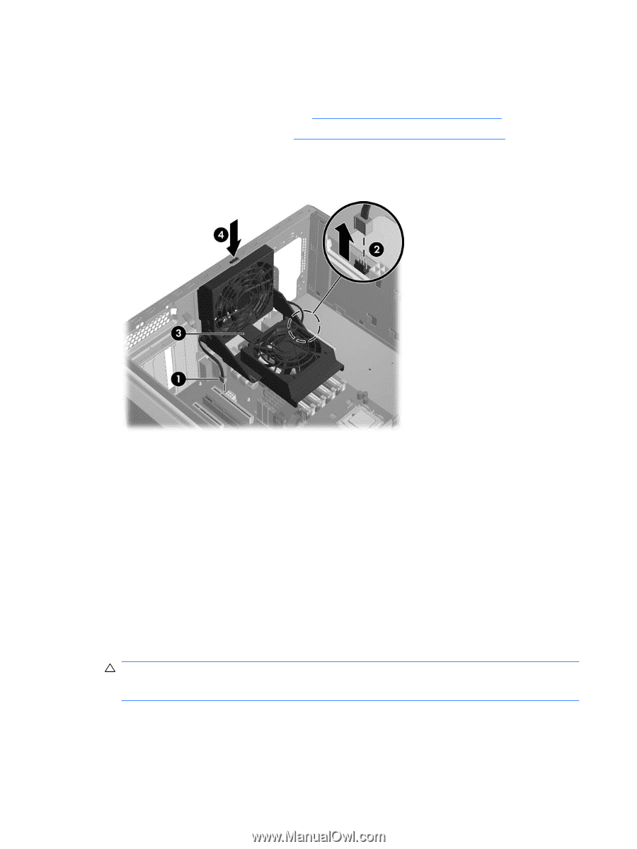
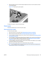
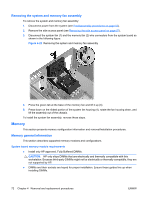
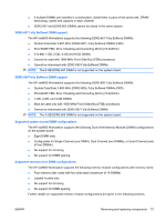
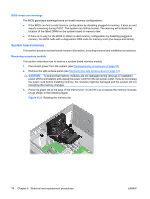
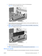
Removing the system and memory fan assembly To remove the system and memory fan assembly: 1. Disconnect power from the system (see Predisassembly procedures on page 52). 2. Remove the side access panel (see Removing the side access panel on page 57). 3. Disconnect the system fan (1) and the memory fan (2) wire connectors from the system board as shown in the following figure. Figure 4-22 Removing the system and memory fan assembly 4. Press the green tab at the base of the memory fan and lift it up (3). 5. Press down on the ribbed portion of the system fan housing (4), rotate the fan housing down, and lift the assembly out of the chassis. To install the system fan assembly, reverse these steps. Memory This section presents memory configuration information and removal/installation procedures. Memory general information This section describes supported memory modules and configurations. System board memory module requirements ● Install only HP approved, Fully Buffered DIMMs. CAUTION: HP only ships DIMMs that are electrically and thermally compatible with this workstation. Because third-party DIMMs might not be electrically or thermally compatible, they are not supported by HP. ● DIMMs and their sockets are keyed for proper installation. Ensure these guides line up when installing DIMMs. 72 Chapter 4 Removal and replacement procedures ENWW
-
 1
1 -
2
-
3
-
4
-
5
-
6
-
7
-
8
-
9
-
10
-
11
-
12
-
13
-
14
-
15
-
16
-
17
-
18
-
19
-
20
-
21
-
22
-
23
-
24
-
25
-
26
-
27
-
28
-
29
-
30
-
31
-
32
-
33
-
34
-
35
-
36
-
37
-
38
-
39
-
40
-
41
-
42
-
43
-
44
-
45
-
46
-
47
-
48
-
49
-
50
-
51
-
52
-
53
-
54
-
55
-
56
-
57
-
58
-
59
-
60
-
61
-
62
-
63
-
64
-
65
-
66
-
67
-
68
-
69
-
70
-
71
-
72
-
73
-
74
-
75
-
76
-
 77
77 -
 78
78 -
 79
79 -
 80
80 -
 81
81 -
 82
82 -
 83
83 -
 84
84 -
 85
85 -
 86
86 -
 87
87 -
88
-
89
-
90
-
91
-
92
-
93
-
94
-
95
-
96
-
97
-
98
-
99
-
100
-
101
-
102
-
103
-
104
-
105
-
106
-
107
-
108
-
109
-
110
-
111
-
112
-
113
-
114
-
115
-
116
-
117
-
118
-
119
-
120
-
121
-
122
-
123
-
124
-
125
-
126
-
127
-
128
-
129
-
130
-
131
-
132
-
133
-
134
-
135
-
136
-
137
-
138
-
139
-
140
-
141
-
142
-
143
-
144
-
145
-
146
-
147
-
148
-
149
-
150
-
151
-
152
-
153
-
154
-
155
-
156
-
157
-
158
-
159
-
160
-
161
-
162
-
163
-
164
-
165
-
166
-
167
-
168
-
169
-
170
-
171
-
172
-
173
-
174
-
175
-
176
-
177
-
178
-
179
-
180
 |
 |