HP xw8600 HP xw8600 Workstation Service and Technical Reference Guide - Page 173
Connector Present Detect, FLP_LOWDEN
 |
View all HP xw8600 manuals
Add to My Manuals
Save this manual to your list of manuals |
Page 173 highlights
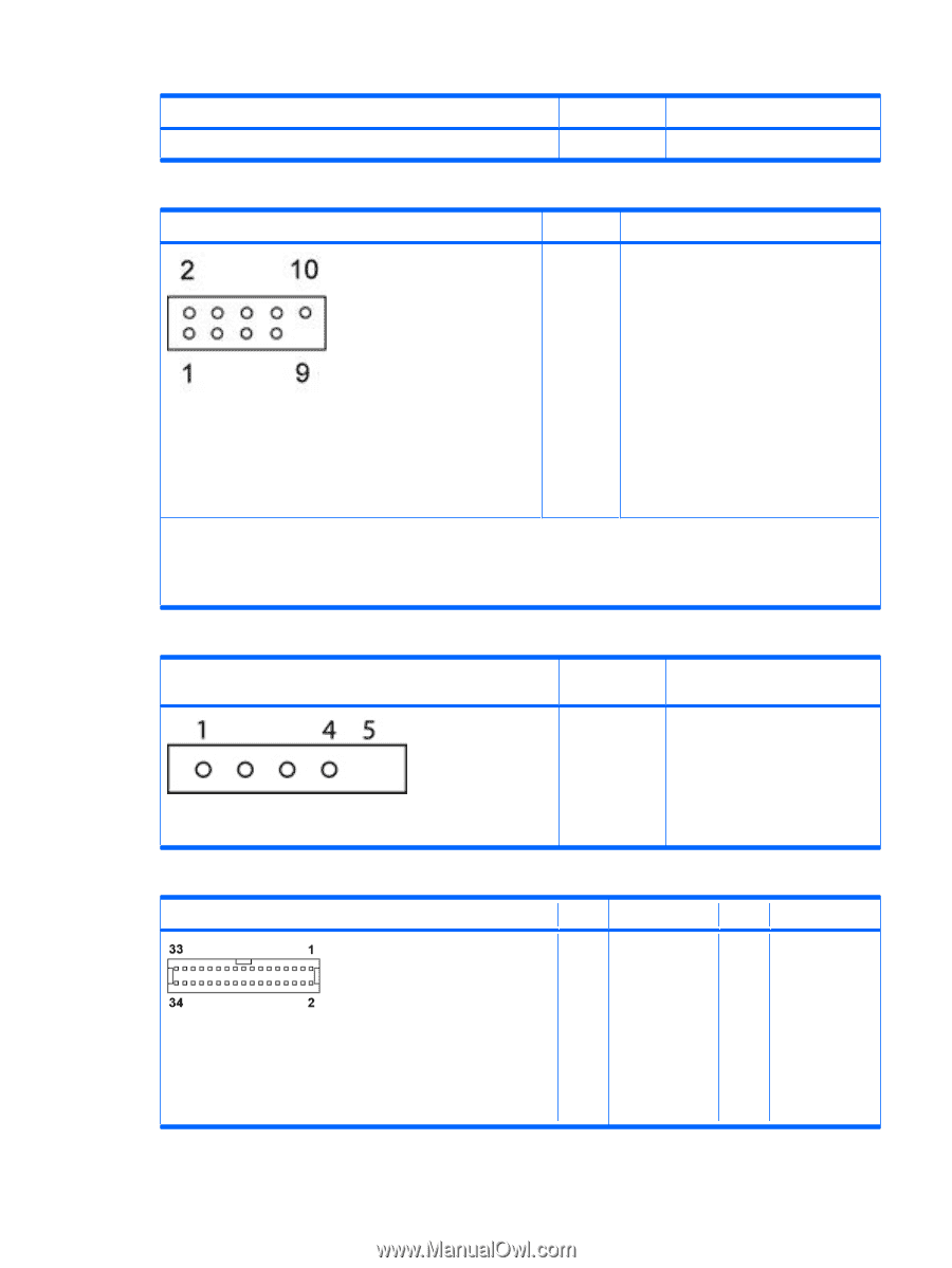
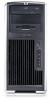
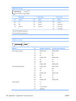
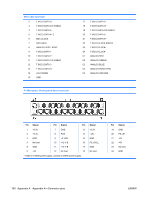
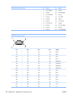
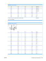
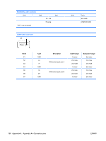
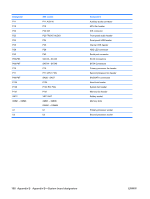
AUX IN system board connector Pin Signal 4 AUX RIGHT Front USB system board 2x5 connector Pin Signal 1 +5V 2 +5V 3 USB6- 4 USB7- 5 USB6+ 6 USB7+ 7 GND 8 GND 9 Key (no pin) 10 Connector Present Detect CAUTION: The 2x5 system board connector can be mated to a wide 2x5 option cable connector or a narrow 1x5 option cable connector. To prevent damage to connectors, connect a narrow 1x5 option cable connector to pins 1,3,5, and 7 only of the 2x5 system board connector. (Pin 9 is not keyed on the system board connector.) P25 Internal USB, CPU heatsink power system board 1x5 connector Pin Signal 1 +5V 2 USB3- 3 USB3+ 4 GND 5 Key (no pin) FDD system board connector Pin Signal 1 Ground 2 FLP_LOWDEN# 3 Key (no pin) 4 FLP_WDO 5 Key (no pin) 6 Unused 7 Ground Pin Signal 18 FLP_DIR# 19 Ground 20 FLP_STEP# 21 Ground 22 FLP_WDATA# 23 Ground 24 FLP_WRTEN# ENWW Connector pin descriptions 163
-
 1
1 -
2
-
3
-
4
-
5
-
6
-
7
-
8
-
9
-
10
-
11
-
12
-
13
-
14
-
15
-
16
-
17
-
18
-
19
-
20
-
21
-
22
-
23
-
24
-
25
-
26
-
27
-
28
-
29
-
30
-
31
-
32
-
33
-
34
-
35
-
36
-
37
-
38
-
39
-
40
-
41
-
42
-
43
-
44
-
45
-
46
-
47
-
48
-
49
-
50
-
51
-
52
-
53
-
54
-
55
-
56
-
57
-
58
-
59
-
60
-
61
-
62
-
63
-
64
-
65
-
66
-
67
-
68
-
69
-
70
-
71
-
72
-
73
-
74
-
75
-
76
-
77
-
78
-
79
-
80
-
81
-
82
-
83
-
84
-
85
-
86
-
87
-
88
-
89
-
90
-
91
-
92
-
93
-
94
-
95
-
96
-
97
-
98
-
99
-
100
-
101
-
102
-
103
-
104
-
105
-
106
-
107
-
108
-
109
-
110
-
111
-
112
-
113
-
114
-
115
-
116
-
117
-
118
-
119
-
120
-
121
-
122
-
123
-
124
-
125
-
126
-
127
-
128
-
129
-
130
-
131
-
132
-
133
-
134
-
135
-
136
-
137
-
138
-
139
-
140
-
141
-
142
-
143
-
144
-
145
-
146
-
147
-
148
-
149
-
150
-
151
-
152
-
153
-
154
-
155
-
156
-
157
-
158
-
159
-
160
-
161
-
162
-
163
-
164
-
165
-
166
-
167
-
 168
168 -
 169
169 -
 170
170 -
 171
171 -
 172
172 -
 173
173 -
 174
174 -
 175
175 -
 176
176 -
 177
177 -
 178
178 -
179
-
180
 |
 |