HP xw8600 HP xw8600 Workstation Service and Technical Reference Guide - Page 121
Removing the system board, Disconnect all cabling from the system board.
 |
View all HP xw8600 manuals
Add to My Manuals
Save this manual to your list of manuals |
Page 121 highlights
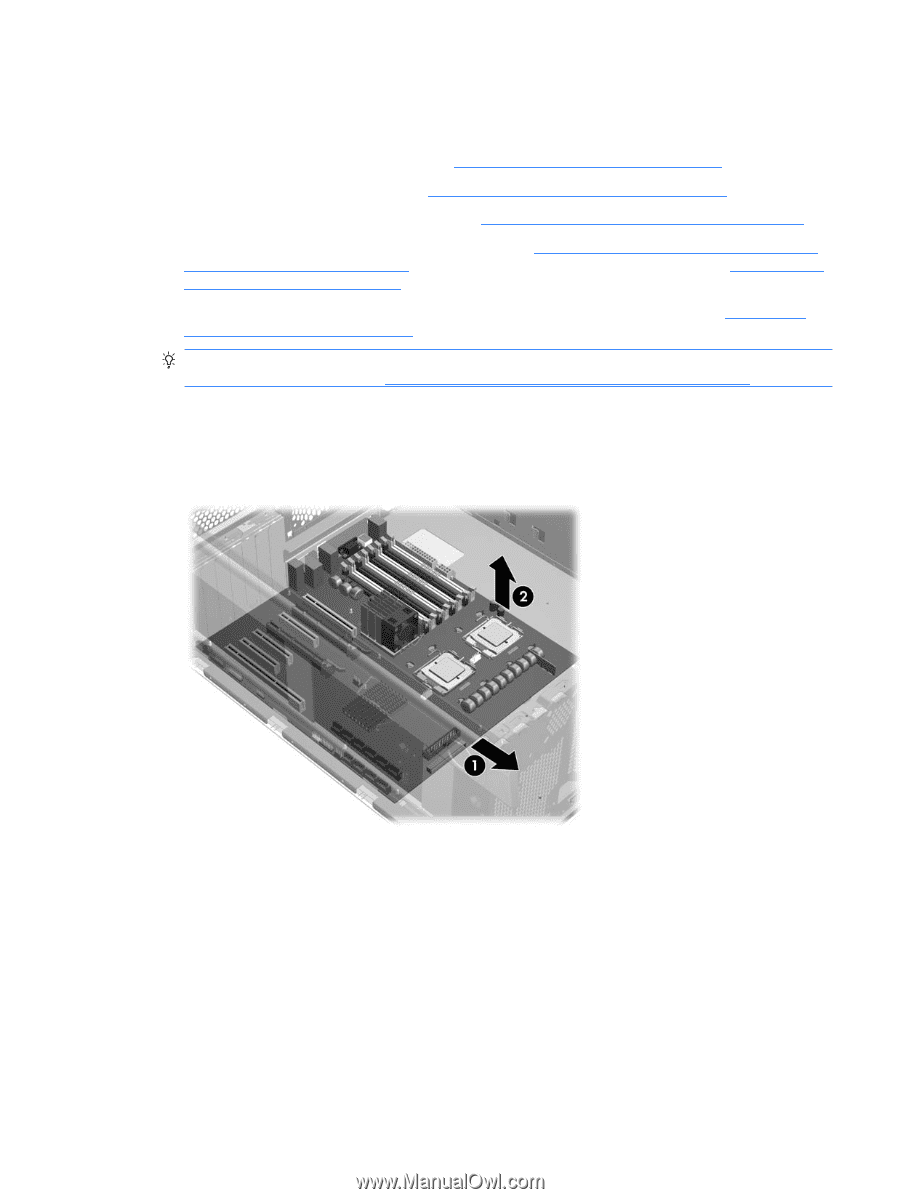
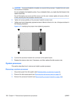
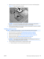
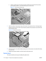
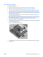
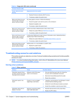
Removing the system board To remove the system board: 1. Disconnect power from the system (see Predisassembly procedures on page 52). 2. Remove the side access panel (see Removing the side access panel on page 57). 3. If a memory riser is installed, remove it (see Removing a memory riser assembly on page 78). 4. Remove expansion boards and graphics cards (see Removing a PCI Express card on page 92, Removing a PCI card on page 95), and then remove the processor heatsink (see Removing the processor heatsink on page 106). 5. If an airflow duct is installed, remove the system and memory fan assembly (see System and memory fan assembly on page 71). TIP: Make a note of the cable connections before disconnecting them from the system board. For more information, refer to Power connections to system components on page 71. 6. Disconnect all cabling from the system board. 7. To disengage the metal mounting standoffs from the chassis (1), slide the system board forward as shown in the following figure. Figure 4-76 Removing the system board 8. Lift the system board out of the chassis, being careful not to damage the cables and rear panel connectors (2). ENWW Removing and replacing components 111
-
 1
1 -
2
-
3
-
4
-
5
-
6
-
7
-
8
-
9
-
10
-
11
-
12
-
13
-
14
-
15
-
16
-
17
-
18
-
19
-
20
-
21
-
22
-
23
-
24
-
25
-
26
-
27
-
28
-
29
-
30
-
31
-
32
-
33
-
34
-
35
-
36
-
37
-
38
-
39
-
40
-
41
-
42
-
43
-
44
-
45
-
46
-
47
-
48
-
49
-
50
-
51
-
52
-
53
-
54
-
55
-
56
-
57
-
58
-
59
-
60
-
61
-
62
-
63
-
64
-
65
-
66
-
67
-
68
-
69
-
70
-
71
-
72
-
73
-
74
-
75
-
76
-
77
-
78
-
79
-
80
-
81
-
82
-
83
-
84
-
85
-
86
-
87
-
88
-
89
-
90
-
91
-
92
-
93
-
94
-
95
-
96
-
97
-
98
-
99
-
100
-
101
-
102
-
103
-
104
-
105
-
106
-
107
-
108
-
109
-
110
-
111
-
112
-
113
-
114
-
115
-
 116
116 -
 117
117 -
 118
118 -
 119
119 -
 120
120 -
 121
121 -
 122
122 -
 123
123 -
 124
124 -
 125
125 -
 126
126 -
127
-
128
-
129
-
130
-
131
-
132
-
133
-
134
-
135
-
136
-
137
-
138
-
139
-
140
-
141
-
142
-
143
-
144
-
145
-
146
-
147
-
148
-
149
-
150
-
151
-
152
-
153
-
154
-
155
-
156
-
157
-
158
-
159
-
160
-
161
-
162
-
163
-
164
-
165
-
166
-
167
-
168
-
169
-
170
-
171
-
172
-
173
-
174
-
175
-
176
-
177
-
178
-
179
-
180
 |
 |