Sony XDSPD2000 User Manual (XDS-PD1000 and XDS-PD2000 Operation Manual for Fir - Page 101
connector, the HD-SDI MONITOR/OUTPUT2SUPER connector, the SD, SDI OUTPUT1 2 SUPER connector
 |
View all Sony XDSPD2000 manuals
Add to My Manuals
Save this manual to your list of manuals |
Page 101 highlights
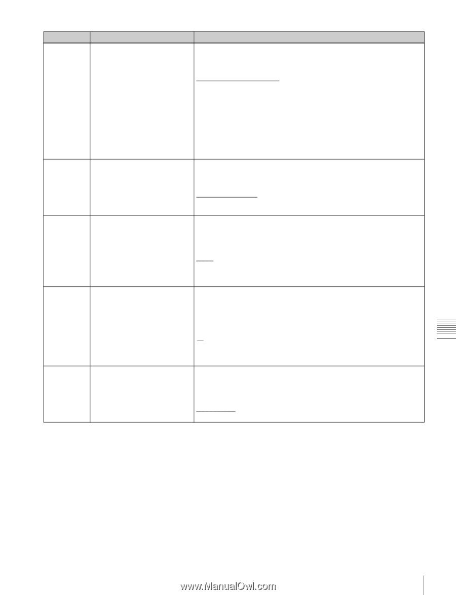
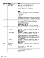
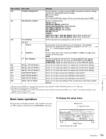
Item number Item name 005 DISPLAY INFORMATION SELECT 006 LOCAL FUNCTION ENABLE 009 CHARACTER TYPE 011 CHARACTER V-SIZE 012 CONDITION DISPLAY ON VIDEO MONITOR Settings Determine the kind of text information to be output from the HD-SDI OUTPUT1 2 (SUPER), SD-SDI OUTPUT1 2 (SUPER), HD-SDI MONITOR/ OUTPUT2 2 (SUPER), SD-SDI MONITOR/OUTPUT2 2 (SUPER), or COMPOSITE OUTPUT MONI/2 connector. time data & status [T&sta]: Time data and the units status. time data & UB [T&UB]: Time data and user bits data. (When "UB" (user bits data) is selected with CNTR SEL on the HOME page of the function menu, the "user bits data" and "time data" arranged in that order are displayed.) time data & CNT [T&CNT]: Time data and counter count. (When "COUNTER" is selected with CNTR SEL on the HOME page of the function menu, the counter count and time data arranged in that order are displayed.) time data & timecode [T&T]: Time data and timecode (TC or VITC) time data only [time]: Time data only Determine which recording and playback control buttons on the front panel are enabled when this unit is controlled from external equipment via a REMOTE (9P) connector. all disable [dis]: All buttons and switches are disabled. stop & eject [st&ej]: Only the STOP button and the EJECT button can operate. all enable [ena]: All buttons and switches are enabled. Determine the type of characters such as timecode output from the HD-SDI OUTPUT1 2 (SUPER) connector, the SD-SDI OUTPUT1 2 (SUPER) connector, the HD-SDI MONITOR/OUTPUT2 2 (SUPER) connector, the SDSDI MONITOR/OUTPUT2 2 (SUPER) connector, or the COMPOSITE OUTPUT MONI/2 connector for superimposed display on the monitor. white: White letters on a black background black: Black letters on a white background white/outline [W/out]: White letters with black outline black/outline [B/out]: Black letters with white outline Determine the vertical size of characters such as timecode output from the HD-SDI OUTPUT1 2 (SUPER) connector, the SD-SDI OUTPUT1 2 (SUPER) connector, the HD-SDI MONITOR/OUTPUT2 2 (SUPER) connector, the SD-SDI MONITOR/OUTPUT2 2 (SUPER) connector, or the COMPOSITE OUTPUT MONI/2 connector for superimposed display on the monitor. ×1: Standard size ×2: 2 times standard size Set this item by selecting the required size while viewing the monitor. Select whether to display disc condition marks in video output from the HDSDI OUTPUT1 2 (SUPER) connector, the SD-SDI OUTPUT1 2 (SUPER) connector, the HD-SDI MONITOR/OUTPUT2 2 (SUPER) connector, the SDSDI MONITOR/OUTPUT2 2 (SUPER) connector, or the COMPOSITE OUTPUT MONI/2 connector. disable [dis]: Do not display enable [ena]: Display. Chapter 7 Menus Setup Menu 101
-
 1
1 -
2
-
3
-
4
-
5
-
6
-
7
-
8
-
9
-
10
-
11
-
12
-
13
-
14
-
15
-
16
-
17
-
18
-
19
-
20
-
21
-
22
-
23
-
24
-
25
-
26
-
27
-
28
-
29
-
30
-
31
-
32
-
33
-
34
-
35
-
36
-
37
-
38
-
39
-
40
-
41
-
42
-
43
-
44
-
45
-
46
-
47
-
48
-
49
-
50
-
51
-
52
-
53
-
54
-
55
-
56
-
57
-
58
-
59
-
60
-
61
-
62
-
63
-
64
-
65
-
66
-
67
-
68
-
69
-
70
-
71
-
72
-
73
-
74
-
75
-
76
-
77
-
78
-
79
-
80
-
81
-
82
-
83
-
84
-
85
-
86
-
87
-
88
-
89
-
90
-
91
-
92
-
93
-
94
-
95
-
 96
96 -
 97
97 -
 98
98 -
 99
99 -
 100
100 -
 101
101 -
 102
102 -
 103
103 -
 104
104 -
 105
105 -
 106
106 -
107
-
108
-
109
-
110
-
111
-
112
-
113
-
114
-
115
-
116
-
117
-
118
-
119
-
120
-
121
-
122
-
123
-
124
-
125
-
126
-
127
-
128
-
129
-
130
-
131
-
132
-
133
-
134
-
135
-
136
-
137
-
138
-
139
-
140
-
141
-
142
-
143
-
144
-
145
-
146
-
147
-
148
-
149
-
150
-
151
-
152
-
153
-
154
-
155
-
156
-
157
-
158
-
159
-
160
-
161
 |
 |