Sony XDSPD2000 User Manual (XDS-PD1000 and XDS-PD2000 Operation Manual for Fir - Page 113
Pulse and Bar [PLSBR], ARIB Color Bars [ARBCB]
 |
View all Sony XDSPD2000 manuals
Add to My Manuals
Save this manual to your list of manuals |
Page 113 highlights
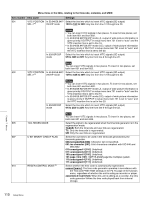
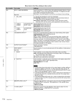
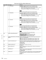
Menu items in the 700s, relating to video control Item number 710 713 715 716 717 718 719 720 Item name INTERNAL VIDEO SIGNAL GENERATOR VIDEO SETUP REFERENCE Sub-item OUTPUT LEVEL In 59.94i/59.94P/ 29.97P mode (UC) In 59.94i/59.94P/ 29.97P mode (J) VIDEO GAIN CONTROL a) b) CHROMA GAIN CONTROL a) b) CHROMA PHASE CONTROL a) b) SETUP LEVEL (59.94i/59.94P/ 29.97P mode)/BLACK LEVEL (50i/ 25P mode) a) b) SYSTEM PHASE SYNC a) SYSTEM PHASE SC a) Settings Select the test signal to be output from the internal test signal generator. When INT SG on page P1 INPUT of the function menu is set to "ON", the internal test signal generator operates to output the selected test signal. This signal can also be recorded. Off [OFF]: Do not output test signal. 75% Color Bars [CB75]: 75% color bar signal 100% Color Bars [CB100]: 100% color bar signal Multi Burst [MLTBS]: Multi-burst signal 10 steps [10STP]: 10-step signal Pulse and Bar [PLSBR]: Pulse and bar signal Ramp [RAMP]: Ramp signal Black [BLACK]: Black signal ARIB Color Bars [ARBCB]: ARIB color bar signal (modify width: 100%) Note "ARIB Color Bar" cannot be specified when SD recording is selected. If "ARIB Color Bar" is selected, the selection is changed to "75% Color Bars" ([CB75]). Set the video setup amount to be added to the composite output signal (in 59.94i/59.94P/29.97P mode only). Add the setup level selected by this item to the output signal. 0.0%, 7.5% Add the setup level selected by this item to the output signal. 0.0%, 7.5% Adjust the video output level of SD video signals output from the SD-SDI OUTPUT, COMPOSITE OUTPUT, or HDMI OUTPUT connectors. -2048 to 0 to 848 Adjust the chroma output level of SD video signals output from the SDSDI OUTPUT, COMPOSITE OUTPUT, or HDMI OUTPUT connectors. -2048 to 0 to 848 Adjust the chroma phase of SD video signals output from the SD-SDI OUTPUT, COMPOSITE OUTPUT, or HDMI OUTPUT connectors. -128 to 0 to 127 Adjust the setup level (black level) of SD video signals output from the SD-SDI OUTPUT, COMPOSITE OUTPUT, or HDMI OUTPUT connectors. -272 to 0 to 272 Adjust the sync phase of SD video signals output from the SD-SDI OUTPUT, COMPOSITE OUTPUT, or HDMI OUTPUT connectors. -128 to 0 to 127 Adjust the subcarrier phase of SD video signals output from the SD-SDI OUTPUT, COMPOSITE OUTPUT, or HDMI OUTPUT connectors. 0 to 511 Chapter 7 Menus Setup Menu 113
-
 1
1 -
2
-
3
-
4
-
5
-
6
-
7
-
8
-
9
-
10
-
11
-
12
-
13
-
14
-
15
-
16
-
17
-
18
-
19
-
20
-
21
-
22
-
23
-
24
-
25
-
26
-
27
-
28
-
29
-
30
-
31
-
32
-
33
-
34
-
35
-
36
-
37
-
38
-
39
-
40
-
41
-
42
-
43
-
44
-
45
-
46
-
47
-
48
-
49
-
50
-
51
-
52
-
53
-
54
-
55
-
56
-
57
-
58
-
59
-
60
-
61
-
62
-
63
-
64
-
65
-
66
-
67
-
68
-
69
-
70
-
71
-
72
-
73
-
74
-
75
-
76
-
77
-
78
-
79
-
80
-
81
-
82
-
83
-
84
-
85
-
86
-
87
-
88
-
89
-
90
-
91
-
92
-
93
-
94
-
95
-
96
-
97
-
98
-
99
-
100
-
101
-
102
-
103
-
104
-
105
-
106
-
107
-
 108
108 -
 109
109 -
 110
110 -
 111
111 -
 112
112 -
 113
113 -
 114
114 -
 115
115 -
 116
116 -
 117
117 -
 118
118 -
119
-
120
-
121
-
122
-
123
-
124
-
125
-
126
-
127
-
128
-
129
-
130
-
131
-
132
-
133
-
134
-
135
-
136
-
137
-
138
-
139
-
140
-
141
-
142
-
143
-
144
-
145
-
146
-
147
-
148
-
149
-
150
-
151
-
152
-
153
-
154
-
155
-
156
-
157
-
158
-
159
-
160
-
161
 |
 |