Sony XDSPD2000 User Manual (XDS-PD1000 and XDS-PD2000 Operation Manual for Fir - Page 27
HD/SD-SDI signal input/output REMOTE 9P remote control 9-pin R/P2, P1
 |
View all Sony XDSPD2000 manuals
Add to My Manuals
Save this manual to your list of manuals |
Page 27 highlights
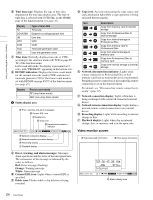
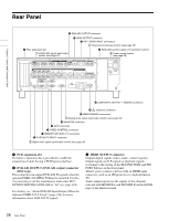
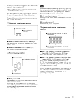
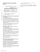
Chapter 2 Names and Functions of Parts d REF. VIDEO INPUT (reference video signal input) connectors (BNC type) The two connectors form a loop-through connection; when a reference video signal is input to the left connector (IN), the same signal is input from the right connector ( ) to a connected device. When no connection is made to the right connector, the left connector is automatically terminated with an impedance of 75 ohms. e Redundant power supply unit installation section When using this unit in a system that requires high reliability, you can back up the unit's power supply by installing the optional XDBK-101 Optional Power Supply. This allows operation to continue even if one of the power supply units fails. To enable continuous operation after failure, set maintenance menu item M22: OPTION SETTING >REDUNDANT PSU to "ON". Note The power supply and XDBK-101 do not support hot swapping. Always turn the main power switch off before exchanging the power supply or adding the XDBK-101. f SYSTEM TC INPUT (system timecode input) connector If you want to input the standard reference timecode signal of a broadcasting station as time data information, use this connector to input it. g REMOTE (9P) (remote control 9-pin) R/P2, P1 connectors (D-sub 9-pin) REMOTE (9P) R/P2 connector: Controls the recording port. Connect a controller that supports the VDCP protocol or the RS-422A Sony 9-pin VTR control protocol. REMOTE (9P) P1 connector: Controls the playback port. Connect a VTR or a controller that supports the VDCP protocol or the RS-422A Sony 9-pin VTR protocol (see page 35). When the unit is set to VTR mode, recording/ playback can be controlled via the P1 connector. h VIDEO CONTROL connector (D-sub-9-pin) Connect an HKDV-900 video control unit. See page 153 for correspondence between setting items of HKDV-900 and setup menu of this unit. i GPIO (general-purpose I/O) connector When you are using this unit in a larger system, such as a playout system, this connector allows you to connect an external device to control this unit's playback, and to return tally and alarm signals to the external device. j MONITOR connector Outputs the same video that appears on the display of this unit's front panel as analog RGB component video signals. This connector is intended for connection to the VGA input connector of a PC monitor. k MAINTENANCE connectors These are the USB connectors for maintenance. l (network) connector (RJ-45 type) This is a 10BASE-T/100BASE-TX/1000BASE-T connector for network connection. CAUTION • For safety, do not connect the connector for peripheral device wiring that might have excessive voltage to this port. Follow the instructions for this port. • When you connect the network cable of the unit to peripheral device, use a shielded-type cable to prevent malfunction due to radiation noise. m COMPOSITE OUTPUT (analog composite video output) 1, MONI/2 connectors (BNC type) Output analog composite video signals. Output signals of the MONI/2 connector are E-E signals or playback signals, according to the setting of the REC/PB2 PORT and PB1 PORT buttons on the front panel.1) In VTR mode, the playback signal is output when the unit is playing a clip, and the E-E signal is output when the unit is recording or set to E-E mode. You can superimpose timecodes or error messages on the output of the MONI/2 connector when CHAR SEL on the HOME page of the function menu is set to "ON". 1) You can set E-E signal output at all times using setup menu item 156 MONITOR OUT SELECT to REC port. See "Basic Operations of the Function Menu" on page 45 for more information about the CHAR SEL setting. 1 HD/SD-SDI signal input/output section 1 HD/SD-SDI INPUT connector 2 HD-SDI OUTPUT1 1, 2 (SUPER) connectors 3 SD-SDI OUTPUT1 1, 2 (SUPER) connectors 4 HD-SDI MONITOR/OUTPUT2 1, 2 (SUPER) connectors 5 SD-SDI MONITOR/OUTPUT2 1, 2 (SUPER) connectors 27 Rear Panel
-
 1
1 -
2
-
3
-
4
-
5
-
6
-
7
-
8
-
9
-
10
-
11
-
12
-
13
-
14
-
15
-
16
-
17
-
18
-
19
-
20
-
21
-
 22
22 -
 23
23 -
 24
24 -
 25
25 -
 26
26 -
 27
27 -
 28
28 -
 29
29 -
 30
30 -
 31
31 -
 32
32 -
33
-
34
-
35
-
36
-
37
-
38
-
39
-
40
-
41
-
42
-
43
-
44
-
45
-
46
-
47
-
48
-
49
-
50
-
51
-
52
-
53
-
54
-
55
-
56
-
57
-
58
-
59
-
60
-
61
-
62
-
63
-
64
-
65
-
66
-
67
-
68
-
69
-
70
-
71
-
72
-
73
-
74
-
75
-
76
-
77
-
78
-
79
-
80
-
81
-
82
-
83
-
84
-
85
-
86
-
87
-
88
-
89
-
90
-
91
-
92
-
93
-
94
-
95
-
96
-
97
-
98
-
99
-
100
-
101
-
102
-
103
-
104
-
105
-
106
-
107
-
108
-
109
-
110
-
111
-
112
-
113
-
114
-
115
-
116
-
117
-
118
-
119
-
120
-
121
-
122
-
123
-
124
-
125
-
126
-
127
-
128
-
129
-
130
-
131
-
132
-
133
-
134
-
135
-
136
-
137
-
138
-
139
-
140
-
141
-
142
-
143
-
144
-
145
-
146
-
147
-
148
-
149
-
150
-
151
-
152
-
153
-
154
-
155
-
156
-
157
-
158
-
159
-
160
-
161
 |
 |